Installation UM353-1
March 2003
8-16
8.4.4 Digital Input and Output Wiring
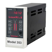
Connections to Digital Input and Digital Input Universal function blocks are shown in Figure 8-14. Wiring for
internal and external power sources is shown. Semiconductor devices can replace the mechanical switches shown.
Wiring guidelines are found in Section 8.4.2.
Digital input commons, e.g. DIN1 (-), are isolated from station common and from case/safety ground.
5
Common Ground Bus
26 Vdc
Earth
Ground
Common
9
Note: See Table 8.1 for
DIN3 terminals.
Controller Circuitry
+
_
(+)
(-)
11
12
(+)
(-)
13
14
+
_
24V
External
Supply
DIN1
DIN2
X03110S1
Transmitter
Supply
Model 353
Rear Terminals
Common Ground Bus
26 Vdc
Earth
Ground
Common
40
Controller Circuitry
+
_
(+)
(-)
36
(+)
(-)
37
38
+
_
24V
External
Supply
DINU1
DINU2
MG000713
35
39
Current
Limiter*
* Limits current to 6 mA maximum.
Current
Limiter*
Transmitter
Supply
Model 353
Rear Terminals
A. DIN1 and 2 B. DINU1 and 2
FIGURE 8-14 Digital Inputs DIN and DINU
Digital output wiring is shown in Figure 8-15. Three diagrams are provided showing current and voltage outputs.
Note the use of transient suppression diodes in Figure 8-15C. Always install a transient suppression component
across a reactive component, such as a relay coil, to protect the semiconductor devices in the Moore 353.
Digital output common, DOUTC, is connected to station common.
 Loading...
