7-7
System Manual
C79000-G8576-C199-06
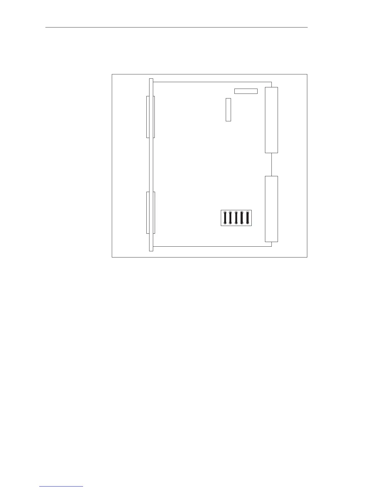
IM 300-5 (-LB11)
X1
X2
X3
X4
M1
P1
Q1
Q2
Q3
Q4 Q5
Figure 7-4 Location of Jumpers on the IM 300-5 (-5LB11) (when Delivered)
You must insert jumpers Q1 to Q4 for addressing in the normal (P) area.
If you insert jumper Q5, the “I/Os not ready” message will be relayed to the
CPU.
All other jumpers must remain in their factory settings.
Shown in the following figures is the centralized communication between
central controller and expansion units, with and without supply of power via
the IM 300 and IM 312.
Jumper
Assignments
Interface Modules
 Loading...

