Interrupts, error messages, diagnostics and system alarms
5.1 Status and error displays
Interface module IM 155-6 DP HF (6ES7155-6BA01-0CN0)
28 Manual, 10/2018, A5E03916550-AD
The LED error display provides information on the cause of the error. After a notification by
means of a flashing signal, the error type and then the error location/error code are displayed
in each case.
The LED error display:
● Is activated during POWER ON and during operation
● Has priority over all other states that are displayed by means of the ERROR- and MAINT-
LED
● Remains on until the cause of the error has been eliminated
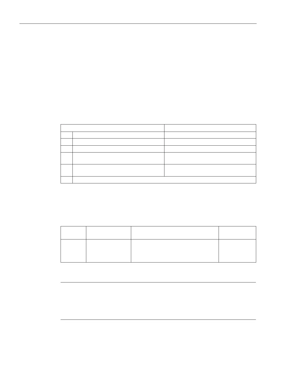
Table 5- 4 Display of error type and error location
ERROR- and MAINT-LED flash 3x with 0.5 Hz
Indication of the error type
2 MAINT-LED flashes with 1 Hz Display of error type (decimal)
ERROR- and MAINT-LED flash 3x with 2 Hz
Indication of error location/error code
4 ERROR-LED flashes with 1 Hz Display of the tens position (decimal) of the
error location/error code
5 MAINT-LED flashes with 1 Hz Display of the units position (decimal) of the
error location/error code
Repetition of 1 to 5 until the cause of the error has been eliminated.
The following table shows the possible causes of error that can occur.
Table 5- 5 Error display
Error location
(ERROR/MAINT)
1 33*
• No server module
• Interruptions on the backplane bus
• Short-circuit on the backplane bus
Check the con-
figuration of the
ET 200SP.
Note
The following LEDs indica
te a short-circuit in the backplane bus supply or in the bus
PWR-LED: On
RN-, ER- and MT-LED: Off

 Loading...


