EasyManuals Logo

Siemens SIMATIC IPC127E User Manual

Siemens SIMATIC IPC127E
100 pages
To Next Page IconTo Next Page
To Previous Page IconTo Previous Page
Page #82 background imageLoading...
Page #82 background image
Hardware description
10.4 Input/output address areas
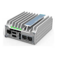
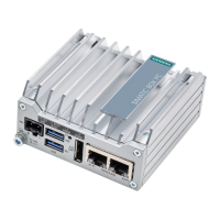
SIMATIC IPC127E
82 Operating Instructions, 01/2019, A5E44296915-AA
10.4.3 MMIO GPIO addresses for LEDs and battery monitoring
COMMUINTY_BASE = Bus 0 Device 0x0d Function 0 Reg. 0x10
GPIO North Community PORT ID = 0xC5
GPIO North West Community PORT ID = 0xC4
GPIO_PADBAR = COMMUNITY_BASE + PORT ID << 16 + 0x500
GPO Reg = GPIO_PADBAR + GPIO_Offset Bit [0] (LEDs)
GPI Reg = GPIO_PADBAR + GPIO_Offset Bit [1] (Battery)
Example: Reg LED_USER1_RD_N_P1V8A = 0xD0C506A0
Function
Community Offset
Direction
Description
LED
0x1A0
Out
Low enable red User LED1
LED
0x1A8
Out
Low enable green User LED1
LED
0x1C8
Out
Low enable red User LED2
LED 0x1D0 Out Low enable green User LED2
LED
0x1E0
Out
Low enable red User LED3
LED
0x198
Out
Low enable green User LED3
LED 0x1C0 Out BIOS boot indicator
Low= OS Control
High= in BIOS Boot Time
Battery
0x1E8
In
High= CMOS battery level below 2.75V
Battery
0x1B8
In
High= CMOS battery level below 2.5V
Battery 0x148 Out High= enable CMOS Battery Check. Must be set
to 1 to read battery status

Table of Contents

Questions and Answers:

Question and Answer IconNeed help?

Do you have a question about the Siemens SIMATIC IPC127E and is the answer not in the manual?

Siemens SIMATIC IPC127E Specifications

General IconGeneral
BrandSiemens
ModelSIMATIC IPC127E
CategoryIndustrial PC
LanguageEnglish

Related product manuals