Overview
1.2 Structure of the devices
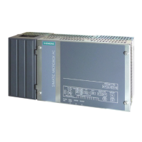
SIMATIC IPC277G
12 Operating Instructions, 08/2021, A5E50059956-AA
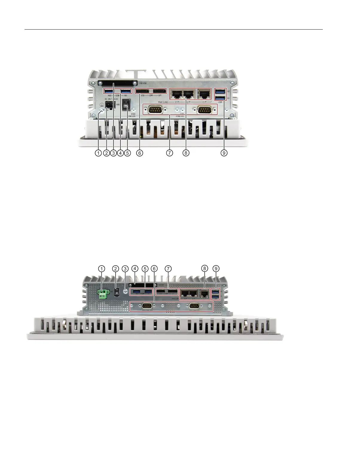
1.2.3 7" and 10" devices - Interfaces and operator controls
Connection for protective conductor
Connection for a 24 VDC power supply
Slot for M.2 NVMe/SATA SSD module
2 × USB 3.1 port, high current
Switch on (position "I"); Switch off (position "O")
2 × DisplayPort connection
2 × Serial interface, 9-pin RS232/RS422/RS485 D-sub connector
3 × RJ45 Ethernet connections for 10/100/1000 Mbps
2 × USB 3.1 port, high current
1.2.4 12", 15", 19", 22" and 24" devices - Interfaces and operator controls
Connection for a 24 VDC power supply
Switch on (position " — "); Switch off (position "C-")
Connection for protective conductor
Slot for M.2 NVMe/SATA SSD module
2 × USB 3.1 port, high current
2 × Serial interface, 9-pin RS232/RS422/RS485 D-sub connector
2 × DisplayPort connection
3 × RJ45 Ethernet connections for 10/100/1000 Mbps
2 × USB 3.1 port, high current



 To Next Page