EasyManuals Logo
Home>Siemens>Industrial PC>Simatic IPC527G

Siemens Simatic IPC527G User Manual

Siemens Simatic IPC527G
123 pages
To Next Page IconTo Next Page
To Previous Page IconTo Previous Page
Page #71 background imageLoading...
Page #71 background image
Technical specifications
7.5 Hardware descriptions
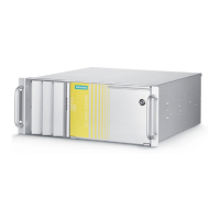
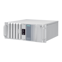
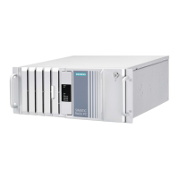
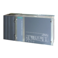
SIMATIC IPC527G
Operating Instructions, 03/2019, A5E45491226-AA
71
7.5.2.7
DIO port
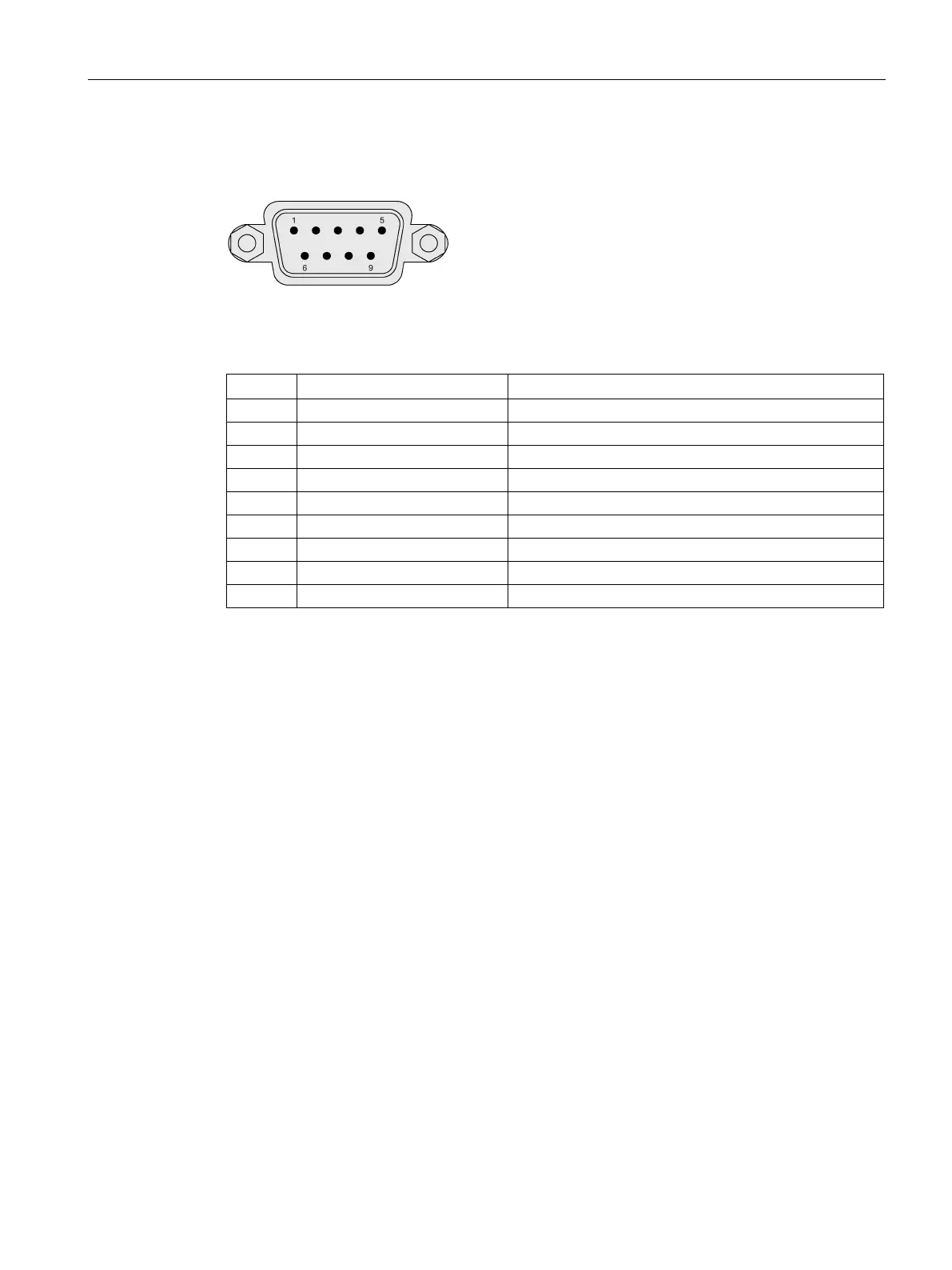
Digital Input (5V TTL) and Ou
tput (5V 12mA)
Pin assignment DIO
Pin
Short description
Meaning
1
DIO_1
Digital Input or Output #1
2
DIO_2
Digital Input or Output #2
3
DIO_3
Digital Input or Output #3
4
DIO_4
Digital Input or Output #4
5
DIO_5
Digital Input or Output #5
6
DIO_6
Digital Input or Output #6
7
DIO_7
Digital Input or Output #7
8
DIO_8
Digital Input or Output #8
9
GND
Ground
Configure DIO pin
You can configure the state of each DIO pin as [Input] mode or [Output] mode in the
Dynamic Digital IO
page of Advanced menu (Page 80) in BIOS.
The DIO setting tool helps you to configure the DIO pin and modify the registers. If you need
DIO setting tool, contact Siemens Technical support (Page 104).

Table of Contents

Questions and Answers:

Question and Answer IconNeed help?

Do you have a question about the Siemens Simatic IPC527G and is the answer not in the manual?

Siemens Simatic IPC527G Specifications

General IconGeneral
BrandSiemens
ModelSimatic IPC527G
CategoryIndustrial PC
LanguageEnglish

Related product manuals