Hardware Information
Release 04/02
7-11
Panel PC 670 Computing Unit, Equipment Manual
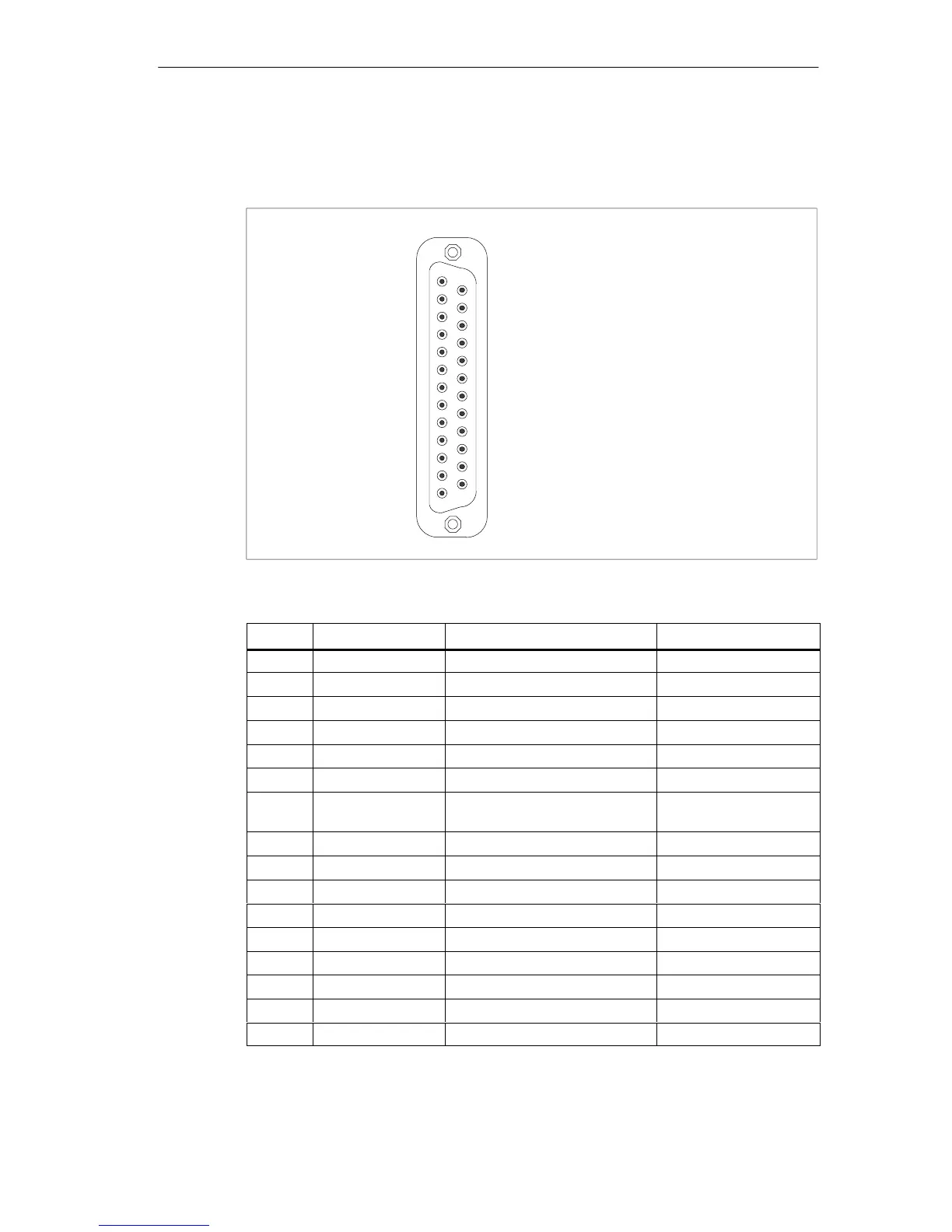
Serial interface COM1 (AG/V24/Modem)
The serial interface (COM 1) of the computing unit is assigned as follows:
1
13
14
25
Figure 7-1 Serial interface COM1 (female)
Pin No.
Short Name Meaning Input/Output
1 - Shield -
2 TxD (D1) Serial transmission data Output
3 RxD (D2) Serial received data Input
4 RTS (S2) Request to send Output
5 CTS (M2) Clear to send Input
6 DSR (M1) Data set ready Input
7 GND (E2) Functional ground (reference
potential)
-
8 DCD (M5) Data carrier detect (carrier) Input
9 +TTY RxD TTY receive Input
10 - 17 - Not assigned -
18 +TTY TxD TTY send Output
19 +20mA Isolated current source -
20 DTR (S1) Data terminal equipment ready Output
21 -TTY TxD TTY send Output
22 RI (M3) Incoming call Input
23-25 - Not assigned -