Hardware Information
Release 04/02
7-32
Panel PC 670 Computing Unit, Equipment Manual
7.6 Wiring Backplane
7.6.1 Design and Theory of Operation
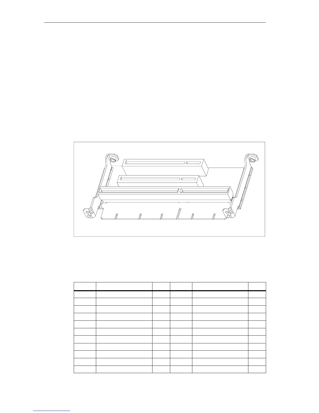
The bus board is designed as a passive link between the motherboard and the
expansion modules. It is mounted with a screw.
The bus board has two ISA slots and two PCI slots, as well as a shared
ISA /PCI slot. The power supply to the expansion cards is effected via the
connection of the bus unit with the basic board. An external power supply (+5V and
+12V) is provided.
Figure 7-10 Wiring Backplane
7.6.2 Pin assignmentI SA slot
Pin No. Short Name Type* Pin No. Short Name Type
A1 IOCHCK I B1 0 V GND
A2 SD 07 I/O B2 RESET DRV O
A3 SD 06 I/O B3 + 5V V
CC
A4 SD 05 I/O B4 IRQ 9 I
A5 SD 04 I/O B5 – 5V V
CC
A6 SD 03 I/O B6 Reserved I
A7 SD 02 I/O B7 – 12V V
CC
A8 SD 01 I/O B8 Reserved I
A9 SD 00 I/O B9 + 12V V
CC
A10 IOCHRDY I B10 0 V GND
A11 AEN O B11 SMEMW# O