Hardware Information
Release 04/02
7-13
Panel PC 670 Computing Unit, Equipment Manual
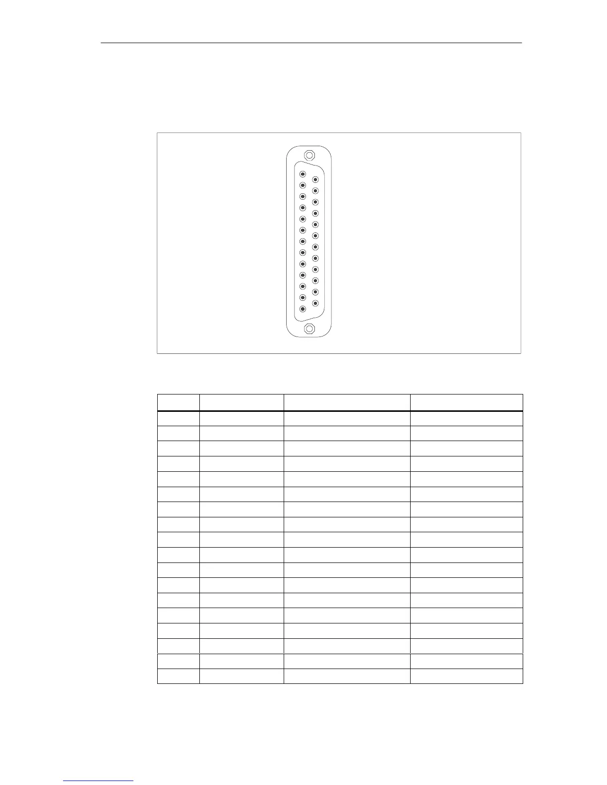
Parallel interface LPT1
The parallel interface (LPT1) of the computing unit is assigned as follows:
1
13
14
25
Figure 7-3 Parallel interface LPT1 (female)
Pin No.
Short Name Meaning Input/Output
1 / Strobe (CLK) Data message Output (open collector)
2 Data bit 0 Data line 0 Output (TTL level)
3 Data bit 1 Data line 1 Output (TTL level)
4 Data bit 2 Data line 2 Output (TTL level)
5 Data bit 3 Data line 3 Output (TTL level)
6 Data bit 4 Data line 4 Output (TTL level)
7 Data bit 5 Data line 5 Output (TTL level)
8 Data bit 6 Data line 6 Output (TTL level)
9 Data bit 7 Data line 7 Output (TTL level)
10 /ACK Acknowledge Input (4.7 kW pull up)
11 BUSY Not ready Input (4.7 kW pull up)
12 PE (PAPER END) No paper Input (4.7 kW pull up)
13 SELECT Device selection Input (4.7 kW pull up)
14 / AUTO FEED Automatic new line Output (open collector)
15 / ERROR Device error Input (4.7 kW pull up)
16 / INIT Reset / Initialization Output (open collector)
17 / SELECT IN Printer selection Output (open collector)
18 - 25 GND Chassis ground -