Hardware Information
Release 04/02
7-23
Panel PC 670 Computing Unit, Equipment Manual
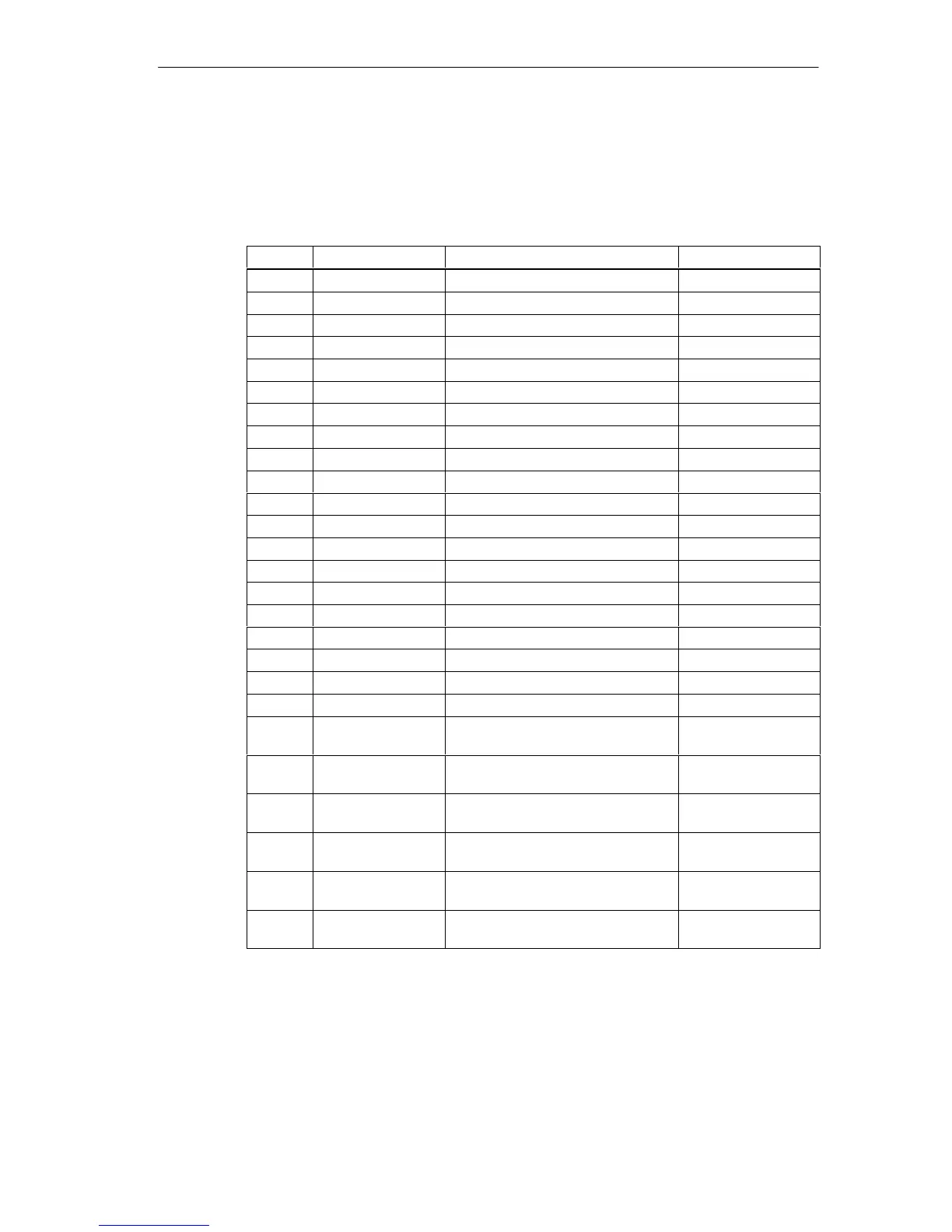
I/O interface for front control elements
All the signals necessary for the connection of front control elements, in addition to
the display and USB ports, are applied to this port. The maximum cable length is
50 cm at a USB data rate of 12 Mbaud.
Pin No. Short Name Meaning Input/Output
1 GND Chassis ground -
2 P12V Power supply for inverter Output
3 BL_ON Backlight on (5V = On) Output
4 P5V_fused +5V ( fused) Output
5 GND Chassis ground -
6 P3V3_fused +3.3V (fused) Output
7 K_CLK Keyboard clock Output
8 K_DATA Keyboard data Input/Output
9 M_CLK Mouse clock Output
10 M_DATA Mouse DATA Input/Output
11 P5V_fused +5V ( fused) Output
12 USB_D1M USB data- channel 1 Input/Output
13 USB_D1P USB Data+ port 1 Input/Output
14 GND Chassis ground -
15 LCD_SEL0 Display type select signal 0 Input
16 LCD_SEL1 Display type select signal 1 Input
17 LCD_SEL2 Display type select signal 2 Input
18 LCD_SEL3 Display type select signal 3 Input
19 RESET_N Reset signal (Low active) Input
20 SPEAKER Connection for system speaker Output
21 HD_LED HD LED, anode with 1kΩ in series
on motherboard
Output
22 DP_LED MPI/DP LED, anode above 1kΩ in
series on motherboard
Output
23 Ethernet_LED Ethernet LED, anode above 1kΩ in
series on motherboard
Output
24 TEMP_ERR LED temperature error, anode with
1kΩ in series on motherboard
Output
25 RUN_R LED watchDog error, anode with
1kΩ in series on motherboard
Output
26 RUN_G LED watchdog o.k., anode with
1kΩ in series on motherboard
Output