$6
$6
$6
$6
3ODQWEXV
352),1(7V\VWHPV352),1(7V\VWHPV
+&,5SRVVLEOH
352),1(7V\VWHP352),1(7V\VWHP
+&,5SRVVLEOH
+&,5SRVVLEOH
&,5SRVVLEOH
(763+$
(763+$
&38
(763+$
(763+$
(763+$
(763+$
(763+$
(763+$
&38
&38
&38
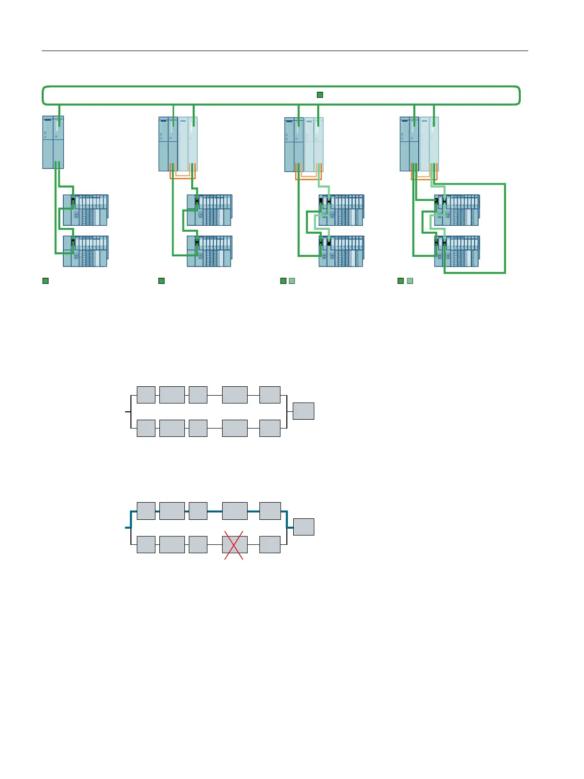
Availability
The block diagram shows the availability of the configuration illustrated above. When both
systems are operating without fault, the block diagram appears as follows:
%XV
+V\VWHP
%XV
&38,0
&38
&3
&3,0
&3
&3
(70
60
The following figure shows how one component may fail without this affecting the operation of
the complete system.
%XV
+V\VWHP
%XV
&38,0
&38
&3
&3,0
&3
&3
(70
60
The system remains available even when one component in part of a line of the redundancy
node fails. There is only one I/O module and therefore no corresponding redundancy node. It
is the weakest link in the complete system's chain.
High availability solutions in PCS 7
4.1 Solutions for the I/O
High Availability Process Control Systems (V9.0)
44 Function Manual, 05/2017, A5E39221836-AA
 Loading...


