Detailed descriptions
16.1 Motherboard
SIMATIC Rack PC 840 V2
16-4 Operating Instructions, Edition 05/2006, A5E00248055-04
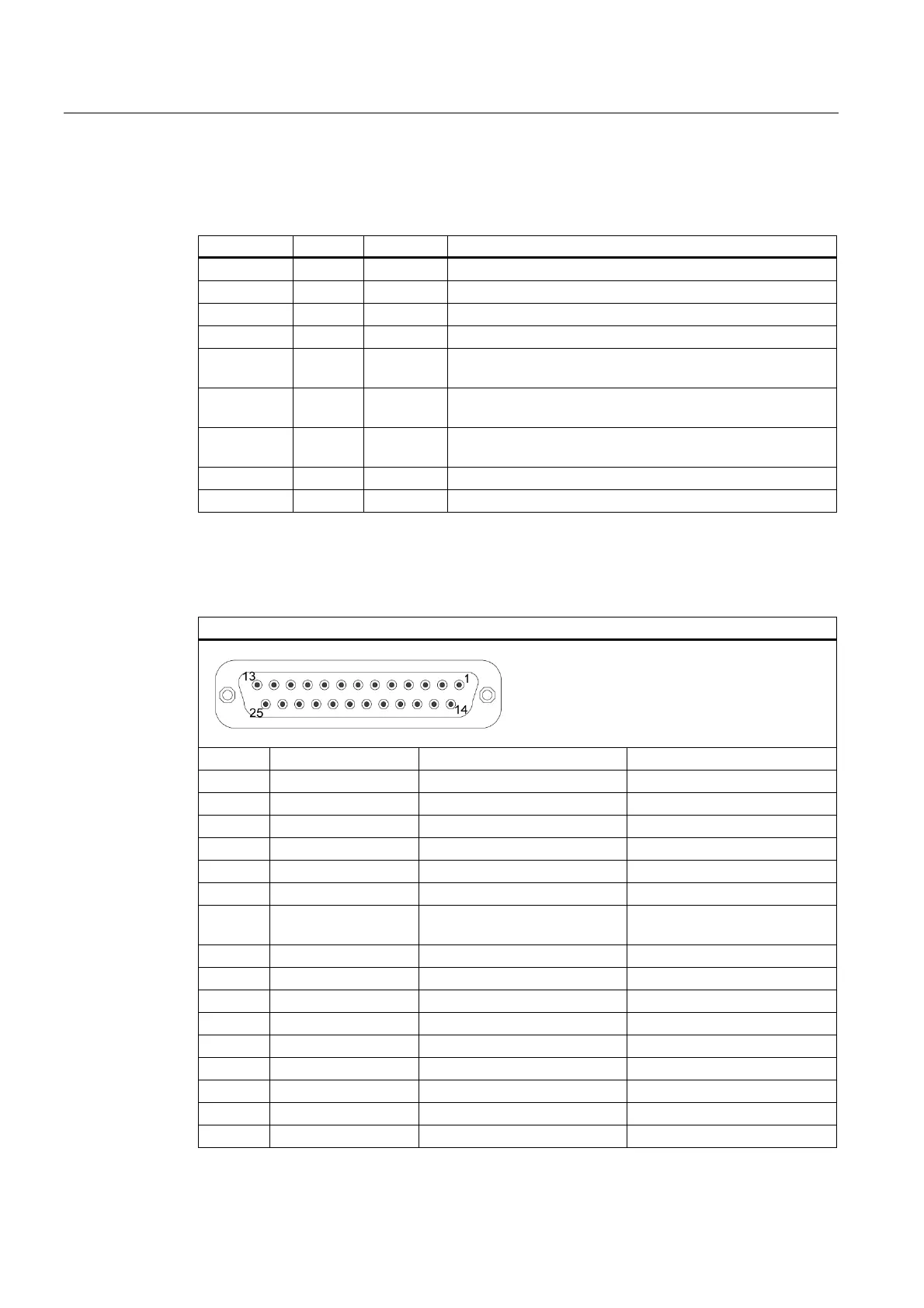
16.1.4 External interfaces
Interface Position Connector Description
COM1 External X30 25-pin socket, V.24/V.28
COM2 External X31 9-pin, standard connector
LPT1 External - 25-pin, standard socket
PS/2 mouse External X22 6-pin, miniature DIN socket
PS/2
keyboard
External X23 6-pin, miniature DIN socket
USB 2.0 External X36 First and second USB channel, additional third internal USB
channel via USB cable to the front panel
PROFIBUS /
MPI
External X400 9-pin, standard socket, potentially isolated port
Ethernet External X700 RJ45
VGA External X303 15-pin socket
Serial port COM 1, X30
The serial port (COM 1) on the device has the following pinout:
Serial port COM 1 (socket)
Pin No. Abbreviations Meaning Input /Output
1 – Shield –
2 TxD (D1) Serial transmit data Output
3 RxD (D2) Serial receive data Input
4 RTS (S2) Request to send Output
5 CTS (M2) Clear to send Input
6 DSR (M1) Ready for operation Input
7 GND (E2) Functional ground (reference
potential)
–
8 DCD (M5) Data carrier detect Input
9 – – –
10–17 – n.c. –
18 – – –
19 – – –
20 DTR (S1) Data terminal ready Output
21 – – –
22 RI (M3) Incoming call Input
23–25 – n.c. –