Detailed descriptions
16.3 Operator panel
SIMATIC Rack PC 840 V2
16-16 Operating Instructions, Edition 05/2006, A5E00248055-04
16.3 16.3 Operator panel
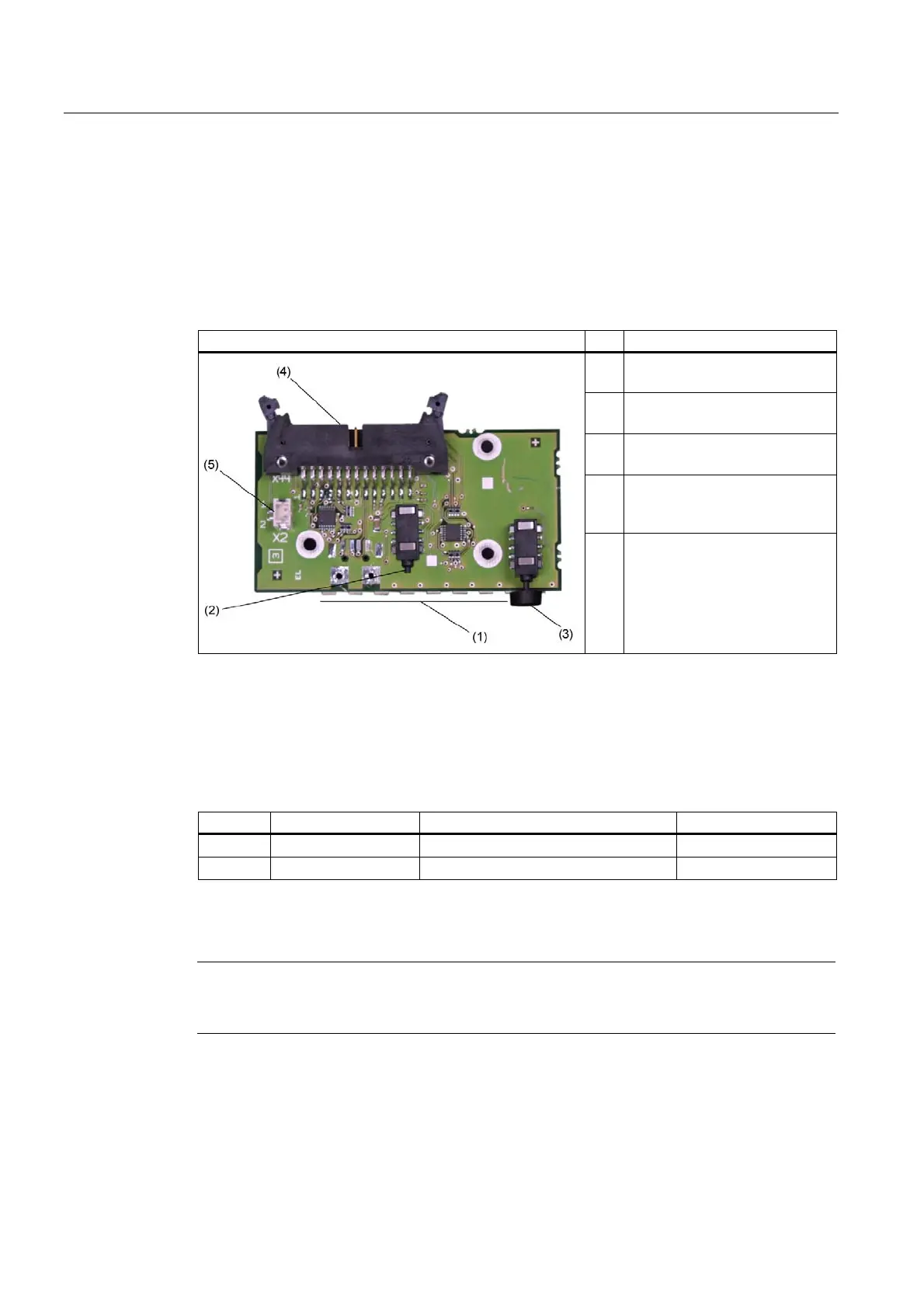
16.3.1 Design
The operator panel is connected to the motherboard with a 26-pin connecting cable.
Operator panel Pos Description
(1) LEDs
Single LED green, red, yellow
(2) Reset button
1-pin button
(3) On/off button
1-pin button
(4) 26-pin male connector
for the connection to the
motherboard
(5) External reset connector
16.3.2 Pin assignment of the OP connectors
External Reset (X30), type: JST B2B-PH-SM3-TB
Pin No. Abbreviation Meaning Input /Output
1 PWRGood External reset, (IO low max. 30 mA)
2 GND Chassis ground
The device is reset when pins 1 and 2 (for example, by means of a button) are short-
circuited. It remains in this state until the short-circuit is cancelled.
Note
For detailed information on the pin assignments of the interfaces, please contact Costumer
Support or the Repair Center.