Wiring
4.3 Terminal and block diagrams
CPU 1512C-1 PN (6ES7512-1CK01-0AB0)
Manual, 12/2017, A5E40898741-AA
91
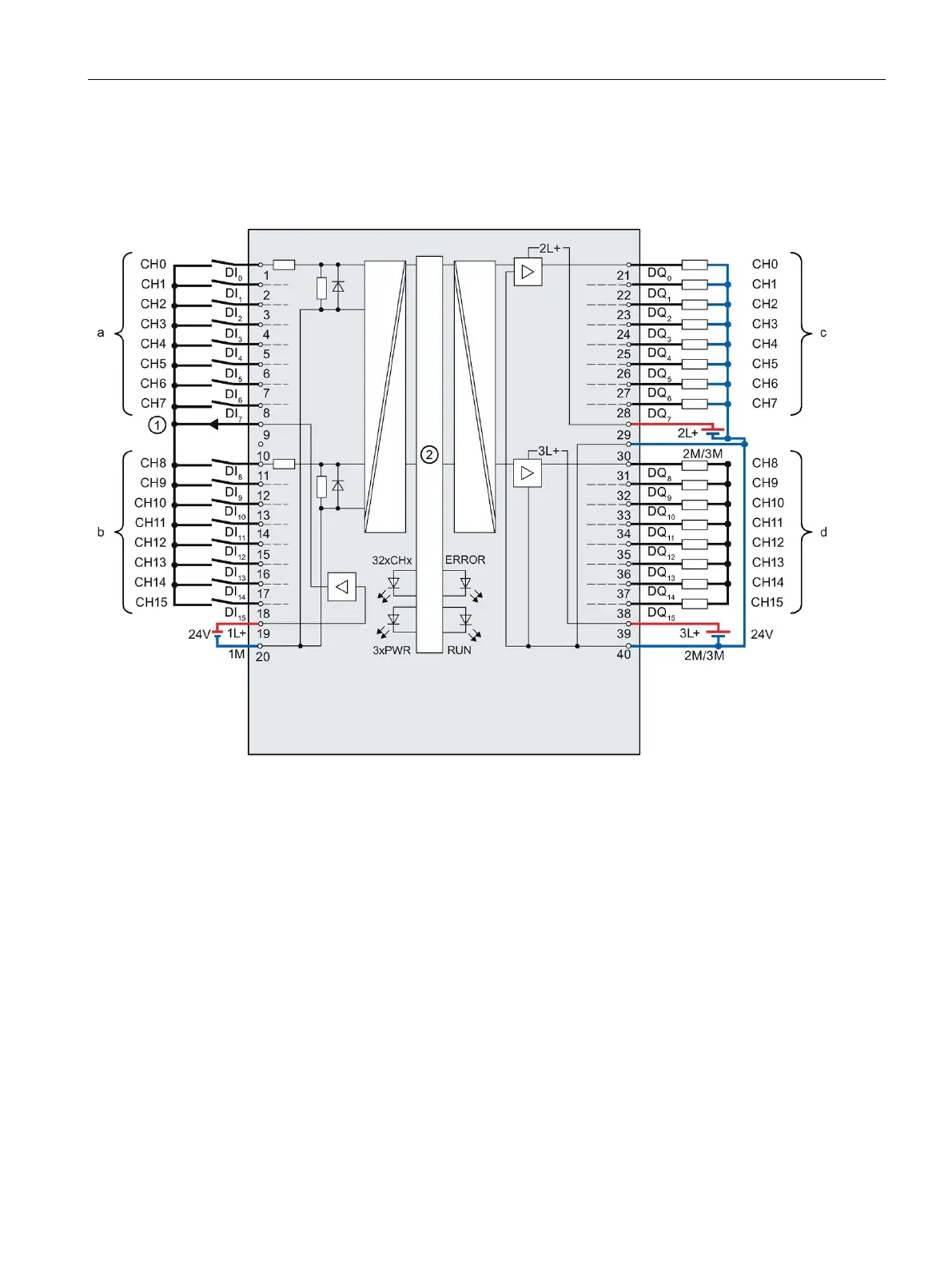
Block diagram and terminal assignment X11
The figure below shows you how to connect the digital on-board I/O X11 and the assignment
of the channels to the addresses (input byte a and b, output byte c and d).
Encoder supply for the digital inputs
Connection for 24 V DC supply voltage
Channel or channel status LED (green)
Status display LED (green)
POWER supply voltage LED (green)
Figure 4-12 Block diagram and terminal assignment of the digital on-board I/O X11

 Loading...


