Technology functions
3.1 High-speed counters
CPU 1512C-1 PN (6ES7512-1CK01-0AB0)
50 Manual, 12/2017, A5E40898741-AA
Assignment of the feedback interface of the high-speed counters
The user program receives current values and status information from the high speed
counter via the feedback interface.
Note
Operation with High_Speed_Counter technology object
The High_Speed_Counter technology object is available for high
-speed counting mode. We
therefore recommend use of the technology object High_Speed_Counter instead of the
control interface/feedback interface for controlling the high speed counter.
For information on configuring the technology object and programming th
e associated
instruction, refer to the S7
-1500, ET 200MP, ET
200SP Counting, measurement and position
detection (
http://support.automation.siemens.com/WW/view/en/59709820) function manual.
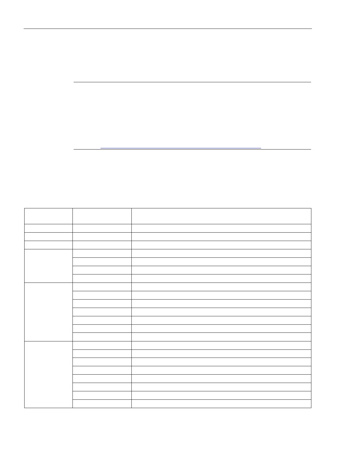
Feedback interface per channel
The following table shows the feedback interface assignment:
Table 3- 4 Assignment of the feedback interface
Offset from start
address
Last Capture value acquired
Byte 12
Bits 3 to 7: Reserve; set to 0
Bit 2: Error when loading via control interface
Bit 1: Incorrect encoder signal
Bit 0: Incorrect supply voltage L+
Byte 13
Bits 6 to 7: Reserve; set to 0
Bit 5: Software gate status
Bit 4: Digital on-board I/O started up and parameters assigned
Bit 3: Load request for Slot 1 detected and executed (toggling)
Bit 2: Load request for Slot 0 detected and executed (toggling)
Bit 1: Reset of event bits active
Byte 14
STS_DI1 Bit 6: Status HSC DI1
STS_DQ1 Bit 4: Status HSC DQ1
Bit 2: Internal gate status
Bit 1: Count pulse detected within last approx. 0.5 s
Bit 0: Direction of last count value change

 Loading...


