Wiring
4.3 Terminal and block diagrams
CPU 1512C-1 PN (6ES7512-1CK01-0AB0)
80 Manual, 12/2017, A5E40898741-AA
Terminal and block diagrams
4.3.1
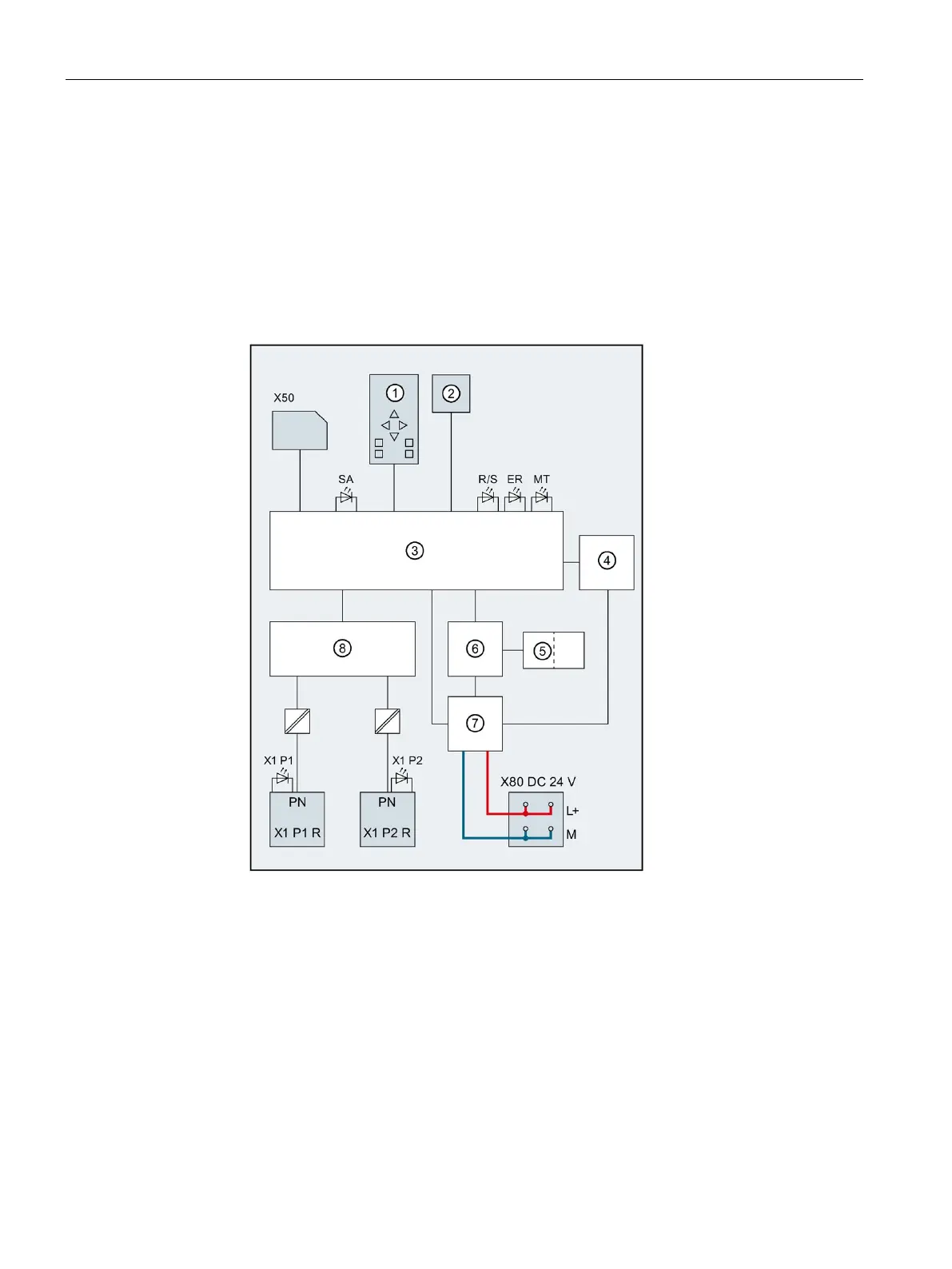
Block diagram of the CPU part
Block diagram
The following figure shows the block diagram of the CPU part.
CPU with control and operating mode
PN X1 P1 R PROFINET interface X1 port 1
PROFINET interface X1 Port 2
Interface to on-board I/O
Interfaces to the backplane bus
RUN/STOP LED (yellow/green)
Figure 4-3 Block diagram of the CPU part

 Loading...


