Interrupts/diagnostics alarms
6.2 Interrupts and diagnostics
CPU 1512C-1 PN (6ES7512-1CK01-0AB0)
138 Manual, 12/2017, A5E40898741-AA
Interrupts and diagnostics of the digital on-board I/O
Diagnostics interrupt
A diagnostics alarm is output for each diagnostics event and the ERROR LED flashes on the
digital on-board I/O. You can read out the diagnostics alarms, for example, in the diagnostics
buffer of the CPU. You can evaluate the error codes with the user program.
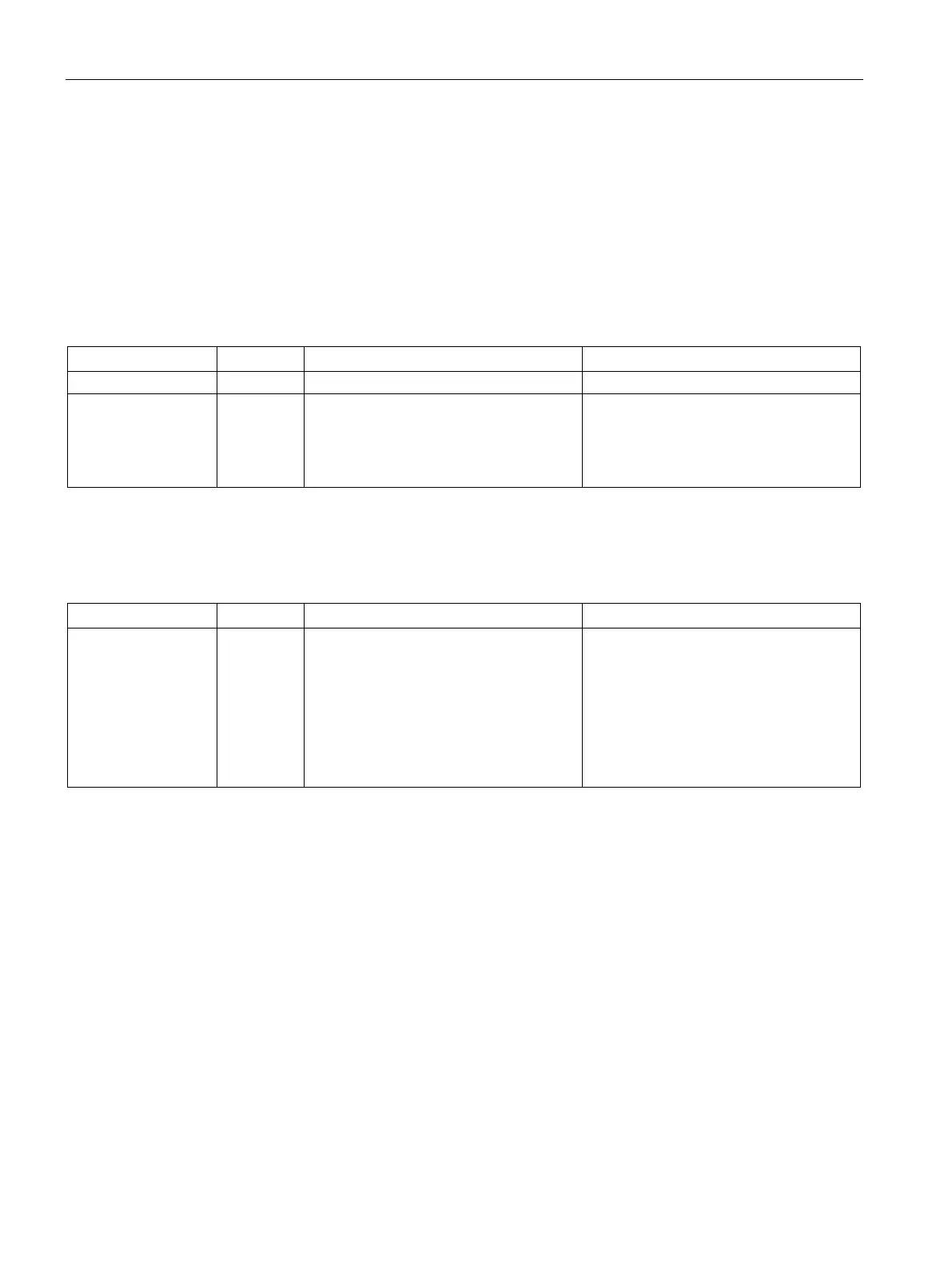
Table 6- 12 Diagnostics alarms, their meaning and corrective measures
Hardware interrupt
lost
16
H
The digital on-board I/O cannot trigger an
interrupt because the previous interrupt
was not acknowledged; possibly a con-
figuration error
• Change the interrupt processing in the
CPU and reconfigure the digital on-
board I/O.
Diagnostic interrupts when using high-speed counters
Table 6- 13 Diagnostics alarms, their meaning and corrective measures
Illegal A/B signal
ratio
500
H
• Time sequence of the A and B signals
of the incremental encoder do not
meet certain requirements.
• Possible causes:
– Signal frequency too high
– Encoder is defective
– Process wiring is incorrect
• Correct the process wiring
• Check the encoder/sensor
• Check the parameter assignment.

 Loading...


