Interrupts/diagnostics alarms
6.2 Interrupts and diagnostics
CPU 1512C-1 PN (6ES7512-1CK01-0AB0)
Manual, 12/2017, A5E40898741-AA
137
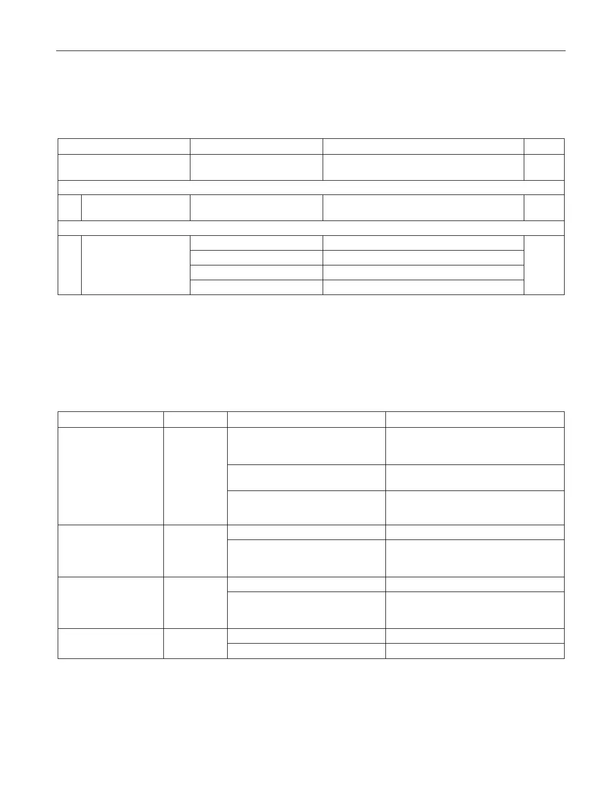
Structure of the additional interrupt information
Table 6- 10 Structure of USI = W#16#0001
USI
(User Structure Identifier)
W#16#0001 Additional hardware interrupt information of the
2
The channel that triggered the hardware interrupt follows.
B#16#00 to B#16#n Number of the event-triggering channel (n =
number of analog on-board I/O channels -1)
1
It is followed by the event that triggered the hardware interrupt.
1
A diagnostics alarm is output for each diagnostics event and the ERROR LED flashes on the
analog on-board I/O. The diagnostics alarms can, for example, be read out in the diagnostics
buffer of the CPU. You can evaluate the error codes with the user program.
Table 6- 11 Diagnostics alarms, their meaning and corrective measures
Wire break 6
H
Resistance of encoder circuit too
high
Use a different encoder type or modify the
wiring, for example, using cables with
Interruption of the cable between the
analog on-board I/O and sensor
Connect the cable
Channel not connected (open)
• Disable diagnostics
• Connect the channel
Overflow 7
H
Check the measuring range
The output value set by the user
program exceeds the valid rated
Correct the output value
Underflow 8
H
Value below measuring range
Check the measuring range
The output value set by the user
program is below the valid rated
Correct the output value
Short-circuit to ground
1
H
Short-circuit of output Q
V
to M
ANA
Eliminate the short-circuit

 Loading...


