Wiring
6.5 Wiring front connectors
S7-300, CPU 31xC and CPU 31x: Installation
Operating Instructions, Edition 08/2004, A5E00105492-05
6-7
6.5 Wiring front connectors
Introduction
The sensors and actuators of your system are connected to the S7-300 AS by means of
front connectors. Wire the sensors and actuators to the relevant front connector and then
plug it into the module.
Front connector versions
Front connectors come in 20-pin and 40-pin versions with screw contacts or spring terminals.
You require 40-pin front connectors for the CPUs 31xC and 32-channel SMs.
Use the following front connectors as required for the module:
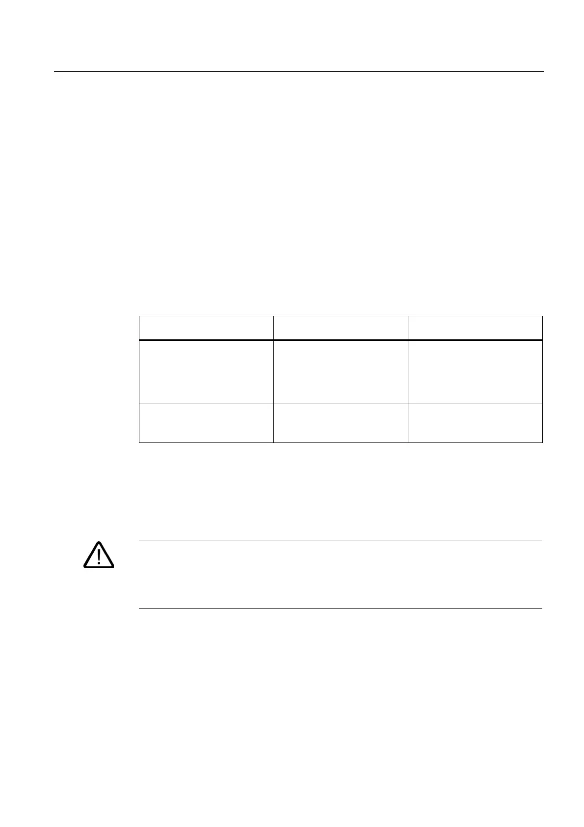
Table 6-5 Assignment of front connectors to modules
Module Front connector with screw
terminals, order no.:
Front connector with spring
terminals, order no.:
SMs
(not 32-channel),
FMs,
Communication module
CP 342-2
6ES7 392-1AJ00-0AA0 6ES7 392-1BJ00-0AA0
SMs
(32-channel) and
CPU 31xC
6ES7 392-1AM00-0AA0 6ES7 392-1BM01-0AA0
Termination on spring terminals
It is quite easy to wire a front connector with spring terminals: Simply insert the screwdriver
vertically into the opening with the red opening mechanism, insert the wire into the terminal
and remove the screwdriver.
Warning
You might damage the spring clamp mechanism of the front connector if you turn the
screwdriver sideways or use the wrong size of screwdriver. Always slide a matching
screwdriver vertically into the desired opening until it reaches the mechanical stop. This
ensures that the spring terminal is fully open.
Tip:
There is a separate opening for test probes up to 2 mm in diameter to the left of the opening
for the screwdriver.
 Loading...


