Maintenance
9.6 Module installation / removal
S7-300, CPU 31xC and CPU 31x: Installation
9-6 Operating Instructions, Edition 08/2004, A5E00105492-05
Note
Project data can generate high data traffic. Especially in RUN mode with read/write access
to the CPU, this can lead to waiting periods of several minutes.
Sample application
When you assign more than one member of your service and maintenance department to
perform maintenance tasks on a SIMATIC PLC, it may prove difficult to provide quick access
to current configuration data to each staff member.
However, CPU configuration data available locally on any CPU that is to be serviced can be
accessed by any member of the service department. They can edit these data and then
release the updated version to all other personnel.
9.6 Module installation / removal
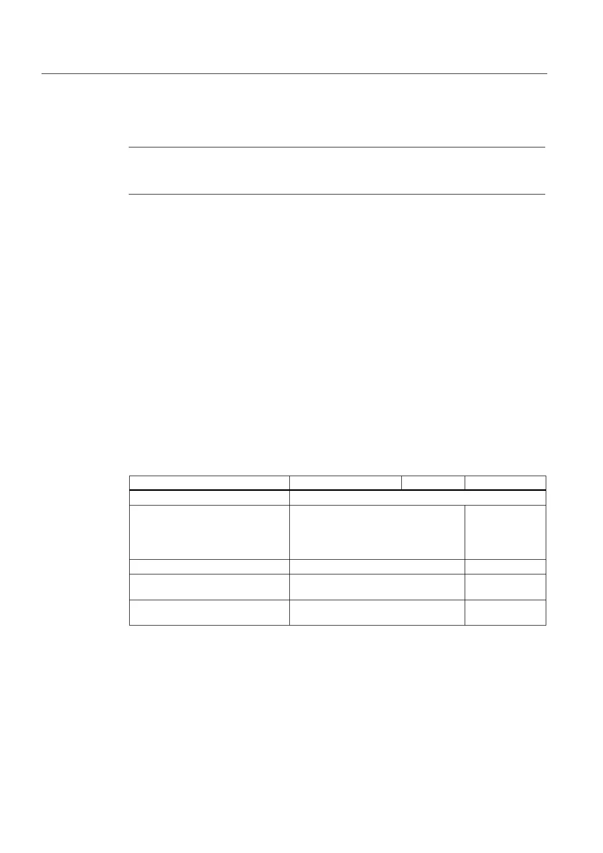
Installation and wiring rules
The table below shows you points to follow when wiring, installing or removing S7-300
modules.
Rules governing ... Power supply ... CPU ... SM/FM/CP
Blade width of the screwdriver 3.5 mm (cylindrical design)
Tightening torque
• Fixing modules to the mounting
rail
• Connecting cables
from 0.8 N/m to 1.1 N/m
from 0.5 N/m to 0.8 N/m
from 0.8 N/m to
1.1 N/m
–
POWER OFF when replacing the ... Yes Yes
S7-300 operating mode when
replacing ...
– STOP
Load voltage OFF when replacing the
...
Yes Yes
 Loading...


