Configuring
4.9 Electrical assembly, protective measures and grounding
S7-300, CPU 31xC and CPU 31x: Installation
Operating Instructions, Edition 08/2004, A5E00105492-05
4-21
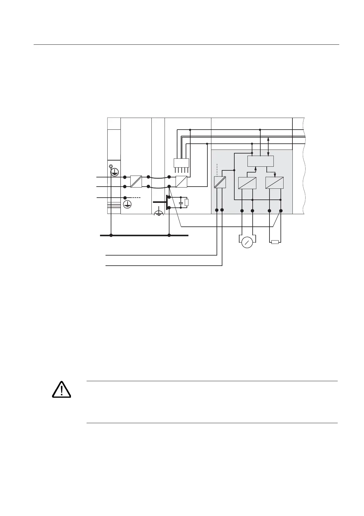
Example: Installing an S7-300 with common potential modules
When using an SM 334 AI 4/AO 2 analog I/O module, connect one of the grounding
terminals M
analog
to the CPU's chassis ground.
The figure below shows an example of such a configuration: An S7-300 with common
potential modules
L+
N
M
L1
L+
M
PS
S7-300 CPU
µ
P
L1
N
U
interna
M
interna
Data
4AI/2AO
PE
1 mm
2
M
analog
M
external
V
A
++
D
A
A
D
Common grounding
line in the cabinet
24 V DC load power supply
4.9.5 Grounding measures
Bonding to ground
Low-impedance connections to ground reduce the risk of electric shock as a result of a
short-circuit or system fault. Low-impedance connections (large surface, large-surface
contact) reduce the effects of interference on the system or the emission of interference
signals. An effective shielding of cables and devices is also a significant contribution.
Warning
All protection class 1 devices, and all larger metal parts, must be bonded to protective
ground. That is the only way to safely protect operators from electrical shock. This also
discharges any interference transmitted from external power supply cables, signal cables or
cables to the I/O devices.
 Loading...


