EasyManuals Logo

Siemens Simatic S7-300 CPU 31xC Series User Manual

Siemens Simatic S7-300 CPU 31xC Series
272 pages
To Next Page IconTo Next Page
To Previous Page IconTo Previous Page
Page #111 background imageLoading...
Page #111 background image
Wiring
6.8 Connecting shielded cables to the shielding contact element
S7-300, CPU 31xC and CPU 31x: Installation
Operating Instructions, Edition 08/2004, A5E00105492-05
6-13
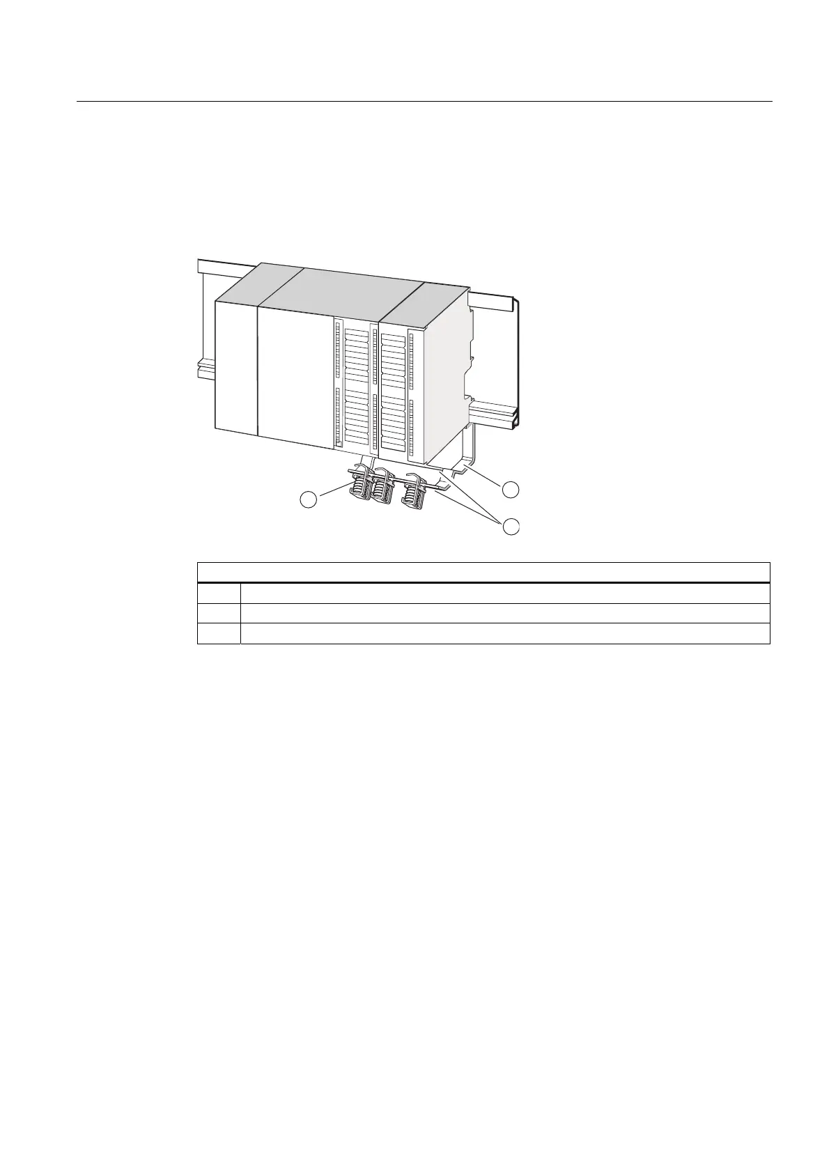
4. The shielding terminal is equipped with a slotted web underneath. Place the shielding
terminal at this position onto the edge of the bracket (see figure below). Push the
shielding terminal down and pivot it into the desired position.
You can install up to 4 shielding terminals on each of the two rows of the shielding
contact element.
CPU
PS
1
1
22
3
The figure illustrates the following
(1) Bracket of shielding contact element
(2) Edge of the bracket where the shielding terminal(s) has to be placed.
(3) Shielding terminals

Table of Contents

Questions and Answers:

Question and Answer IconNeed help?

Do you have a question about the Siemens Simatic S7-300 CPU 31xC Series and is the answer not in the manual?

Siemens Simatic S7-300 CPU 31xC Series Specifications

General IconGeneral
SeriesS7-300 CPU 31xC
Power Supply24 V DC
Communication InterfacesMPI, PROFIBUS DP
Programming LanguagesLAD, STL, FBD, SCL
Operating Temperature0°C to +60°C
Memory48 KB - 512 KB
Dimensions40 x 125 x 130 mm (varies by model)

Related product manuals