Configuring
4.11 Planning subnets
S7-300, CPU 31xC and CPU 31x: Installation
4-40 Operating Instructions, Edition 08/2004, A5E00105492-05
4.11.2.6 Cable lengths of MPI and PROFIBUS subnets
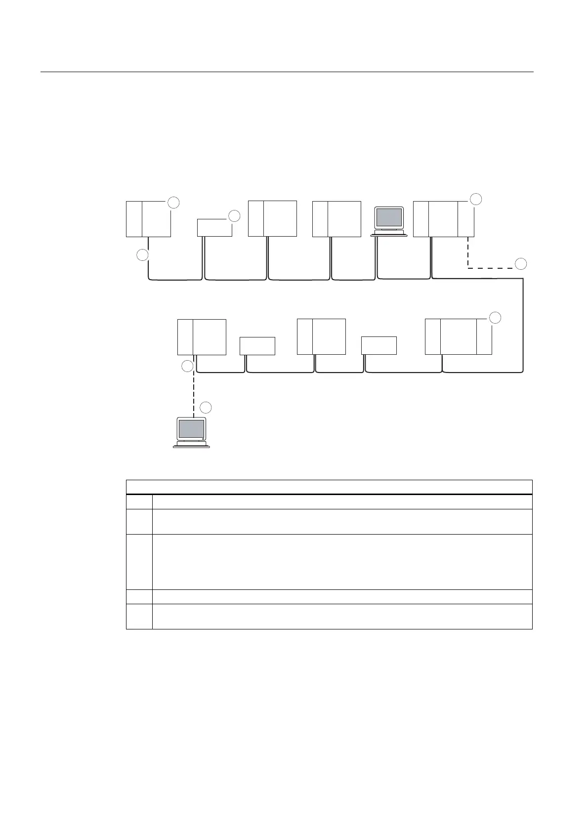
Example: Installation of an MPI subnet
The figure below shows you the block diagram of a MPI subnet.
PG
PG
OP 27
S7-300
3
SF
BUSF
DC5V
FRCE
RUN
STOP
CPU
PS
MPI-addr. 2
S7-300
CPU
PS
CPU
3
S7-300
CPU
PS
CPU
3
S7-300
CPU
PS
CPU
CP
3
S7-300
CPU
PS
CPU
3
S7-300
CPU
PS
CPU
OP 27
3
S7-300
CPU
PS
CPU
FM
MPI-addr. 1
MPI-addr. 3 MPI-addr. 4
MPI-addr. 5 MPI-addr. 6
MPI-addr. 7
PROFIBUS
MPI-addr. 9MPI-addr. 8MPI-addr. 10MPI-addr. 11MPI-addr. 12
OP 27
MPI-addr. 13
MPI-addr. 0
2
2
1
1
5
4
3
3
Key to numbers in the figure
(1) Terminating resistor enabled.
(2) S7-300 and OP 27 have subsequently been connected to the MPI subnet using their default
MPI address.
(3) CPU 31xC, 312, 314, 315-2 DP
You can also assign user-specific MPI addresses to the CPs/FMs at these CPUs.
CPU 317-2 DP
CPs and FMs do not have their own MPI address in this CPU.
(4) In addition to the MPI address, the CP also has a PROFIBUS address (7 in this case).
(5) Connected via a stub cable using the default MPI address for commissioning/maintenance
only

 Loading...


