Configuring
4.9 Electrical assembly, protective measures and grounding
S7-300, CPU 31xC and CPU 31x: Installation
4-24 Operating Instructions, Edition 08/2004, A5E00105492-05
4.9.6 Overview: Grounding
CPU 31xC
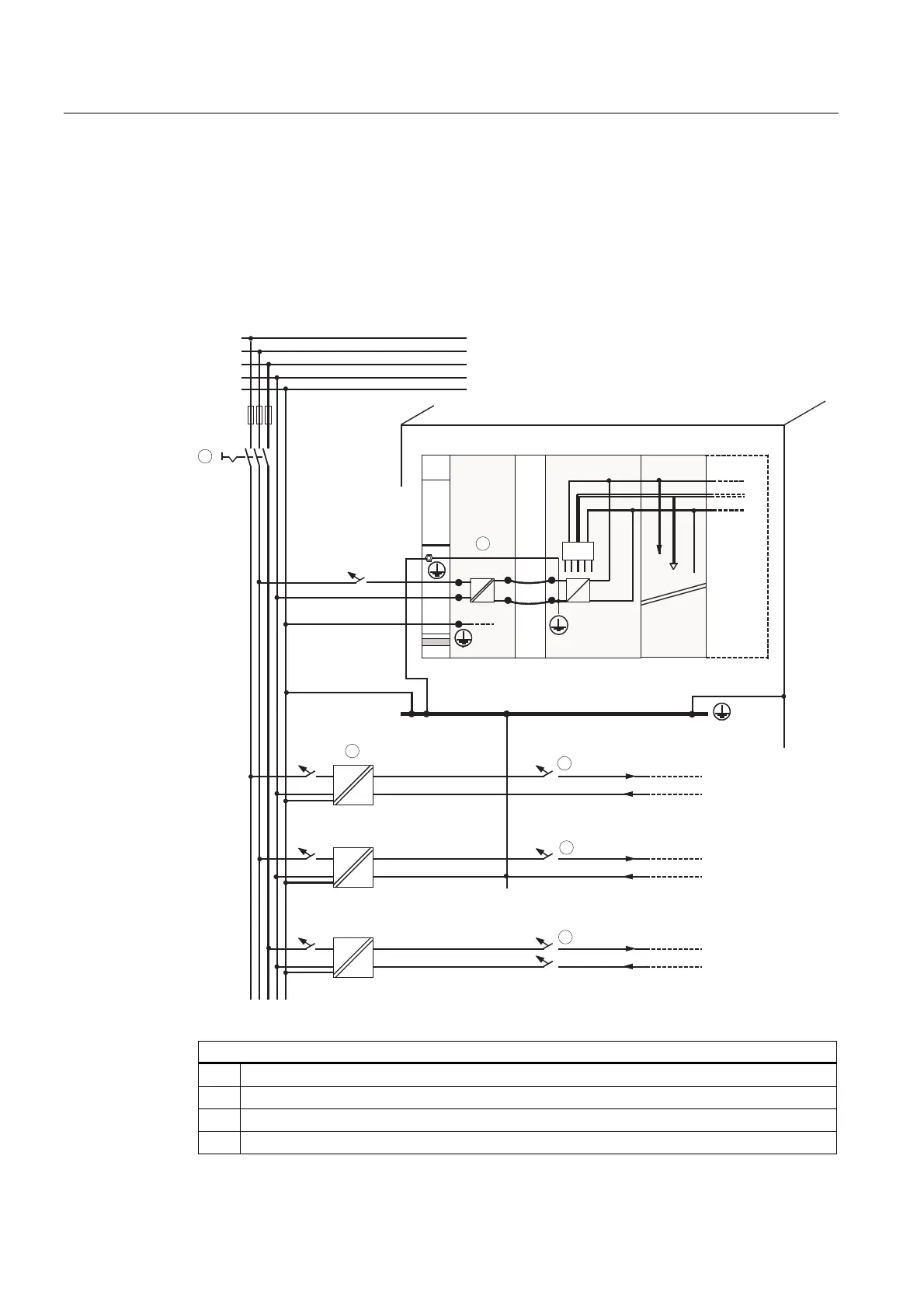
The figure below shows you the complete assembly of an S7-300 with CPU 31xC with a
power supply from TN-S mains. Apart from powering the CPU, the PS 307 also supplies the
load current for the 24 VDC modules. Note: The layout of the power connections does not
correspond with their physical arrangement; it was merely selected to give you a clear
overview.
Cabinet
Profile rail
PS
CPU
SM
L1
N
L+
M
µP
AC
AC
AC
AC
DC
DC
L1
L2
L3
N
PE
1
Low-voltage distribution
e.g. TN-S system (3 x 400 V)
Common grounding line in the cabinet
Load circuit
24 to 230 V AC for AC modules
Load circuit
5 to 60 V DC non-isolated DC modules
Load circuit
5 to 60 V DC for isolated DC modules
Signal modules
1
3
2
2
2
4
4
Table 4-10 Connecting the load voltage reference potential
The figure illustrates the following
(1)
The main switch
(2)
The short-circuit / overload protection
(3)
The load current supply (galvanic isolation)
(4)
This connection is made automatically for the CPU 31xC

 Loading...


