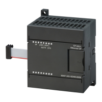
S7-300, CPU 31xC and CPU 31x: Installation
Operating Instructions, Edition 08/2004, A5E00105492-05
vii
Table of contents
Preface ......................................................................................................................................................iii
1 Guide to the S7-300 documentation ....................................................................................................... 1-1
2 Installation Order .................................................................................................................................... 2-1
3 S7-300 components................................................................................................................................ 3-1
3.1 Example of an S7-300 configuration..........................................................................................3-1
3.2 Overview of the vital modules of an S7-300 .............................................................................. 3-2
4 Configuring ............................................................................................................................................. 4-1
4.1 Overview .................................................................................................................................... 4-1
4.2 Basic engineering principles ...................................................................................................... 4-1
4.3 Component dimensions ............................................................................................................. 4-4
4.4 Required clearances .................................................................................................................. 4-6
4.5 Arrangement of modules on a single rack ................................................................................. 4-7
4.6 Distribution of modules to several racks ....................................................................................4-8
4.7 Selection and installation of cabinets....................................................................................... 4-11
4.8 Example: Selecting a cabinet................................................................................................... 4-14
4.9 Electrical assembly, protective measures and grounding ....................................................... 4-15
4.9.1 Grounding concept and overall structure................................................................................. 4-15
4.9.2 Installing an S7-300 with grounded reference potential .......................................................... 4-16
4.9.3 Configuring an S7-300 with ungrounded reference potential (not CPU 31xC)........................ 4-17
4.9.4 Modules with isolated or common potential?........................................................................... 4-19
4.9.5 Grounding measures ............................................................................................................... 4-21
4.9.6 Overview: Grounding ............................................................................................................... 4-24
4.10 Selecting the Load Power Supply............................................................................................ 4-26
4.11 Planning subnets ..................................................................................................................... 4-28
4.11.1 Overview .................................................................................................................................. 4-28
4.11.2 Configuring MPI and PROFIBUS subnets ............................................................................... 4-30
4.11.2.1 Overview .................................................................................................................................. 4-30
4.11.2.2 Basic principles of MPI and PROFIBUS subnets .................................................................... 4-30
4.11.2.3 Multi-Point Interface (MPI) ....................................................................................................... 4-33
4.11.2.4 PROFIBUS DP interface.......................................................................................................... 4-34
4.11.2.5 Network components of MPI/DP and cable lengths ................................................................ 4-35
4.11.2.6 Cable lengths of MPI and PROFIBUS subnets ....................................................................... 4-40
4.11.3 Configuring PROFINET subnets.............................................................................................. 4-45
4.11.3.1 Overview .................................................................................................................................. 4-45
4.11.3.2 PROFINET nodes .................................................................................................................... 4-45
4.11.3.3 Integration of field bus systems in PROFINET ........................................................................ 4-48
4.11.3.4 PROFINET IO and PROFINET CBA ....................................................................................... 4-49
4.11.3.5 PROFINET cable lengths and network expansion .................................................................. 4-54

 Loading...


