Configuring
4.3 Component dimensions
S7-300, CPU 31xC and CPU 31x: Installation
Operating Instructions, Edition 08/2004, A5E00105492-05
4-5
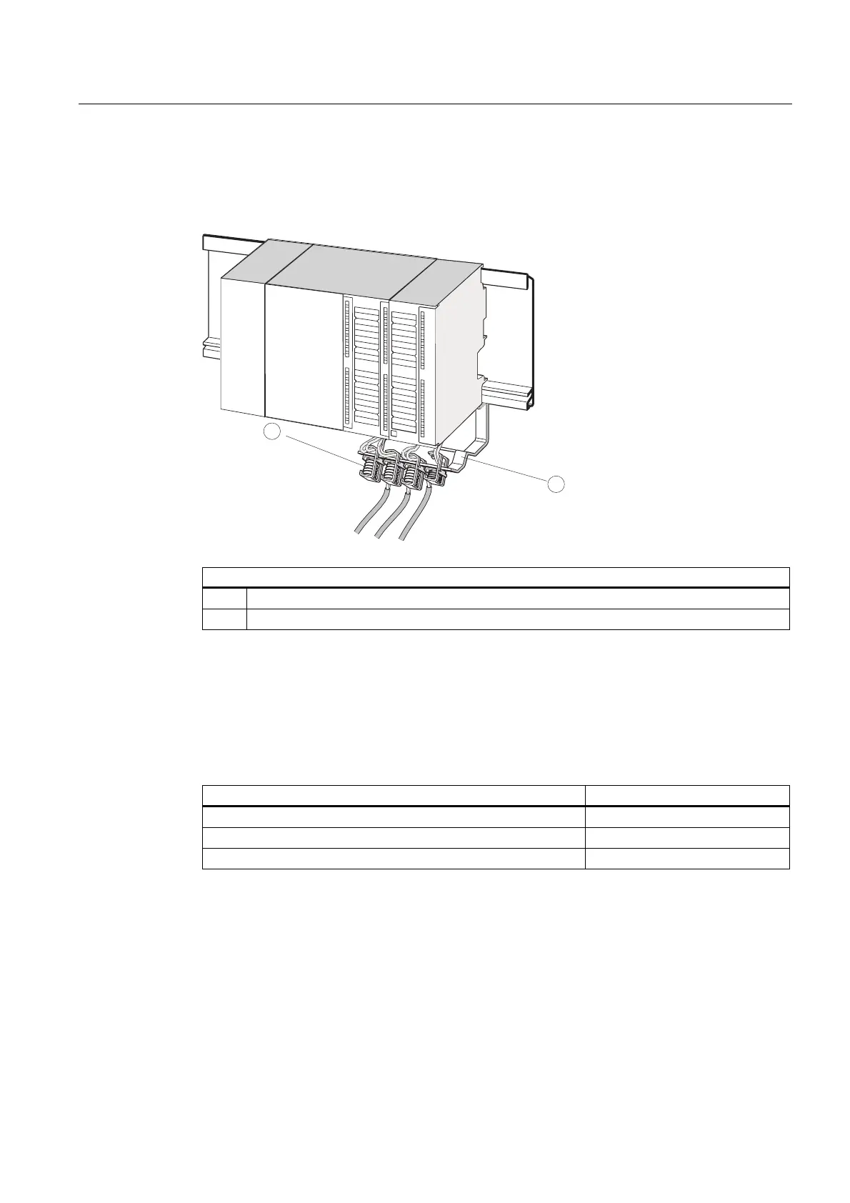
Shielding contact element
The direct contact between the shielding contact element and the mounting rail makes it
easy for you to connect all shielded cables of your S7 modules to ground.
CPU
PS
1
2
The figure illustrates the following
(1) Shielding terminals
(2) The bracket.
Mount the bracket (order no. 6ES5 390-5AA0-0AA0) to the rail using the two screw bolts. If
you use a shielding contact element, the specified dimensions are measured from the base
of the element.
• Width of the shielding contact element: 80 mm
• Mountable shielding terminals per shielding contact element max. 4
Table 4-3 Shielding terminals - Overview
Cable with shielding diameter Shielding terminal order no.
Cable with 2 mm to 6 mm shielding diameter 6ES7 390–5AB00–0AA0
Cable with 3 mm to 8 mm shielding diameter 6ES7 390–5BA00–0AA0
Cable with 4 mm to 13 mm shielding diameter 6ES7 390–5CA00–0AA0

 Loading...


