Configuring
4.4 Required clearances
S7-300, CPU 31xC and CPU 31x: Installation
4-6 Operating Instructions, Edition 08/2004, A5E00105492-05
4.4 Required clearances
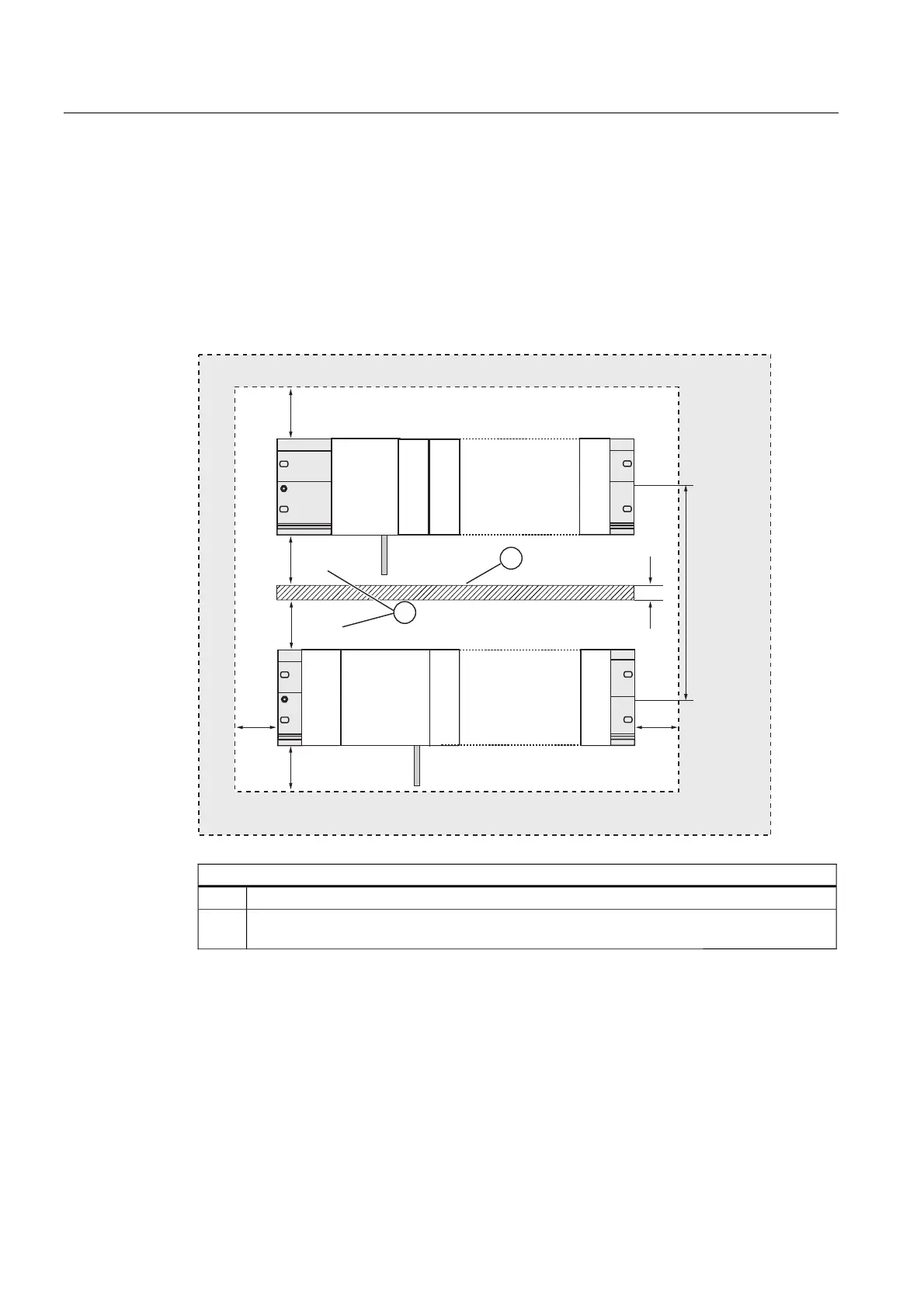
You must maintain the clearance shown in the figure in order to provide sufficient space for
installing the modules, and to allow the dissipation of heat generated by the modules.
The S7-300 assembly on multiple racks shown in the figure below shows the clearance
between racks and adjacent components, cable ducts, cabinet walls etc.
For example, when routing your module wiring through cable duct, the minimum clearance
between the bottom of the shielding contact element and the cable duct is 40 mm.
PP
PP
PP
PP
PPD
D
PP
PP
60
60
60
60
60
&38
36
&38
The figure illustrates the following
(1) Wiring with cable duct
(2) Minimum clearance between the cable duct and the bottom edge of the shielding contact
element is 40 mm

 Loading...


