Addressing
7.2 User-specific addressing of modules
S7-300, CPU 31xC and CPU 31x: Installation
7-4 Operating Instructions, Edition 08/2004, A5E00105492-05
When the first digital module is located in slot 4, its default start address is 0. The start
address of each further digital module increments by the count of 4.
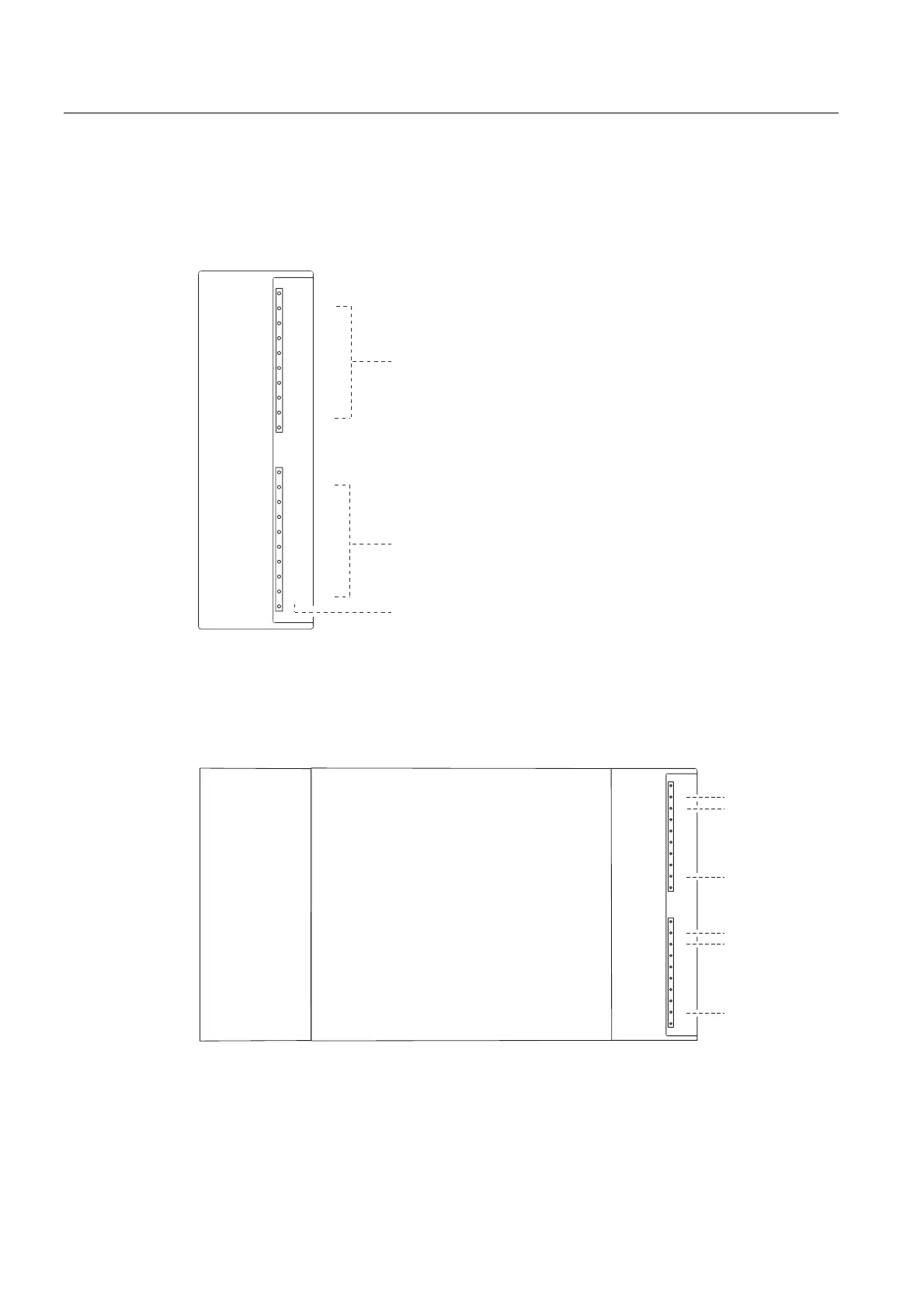
The figure below shows you how the scheme by which the addresses of the various
channels of a digital module are derived.
0
1
2
3
4
5
6
7
0
1
2
3
4
5
6
7
Bit address:
Module start address
Byte address:
Module start address + 1
Bit address
An example of digital modules
The example in the figure below shows which default addresses are derived when a digital
module is located in slot 4 (that is, when the module start address is 0). Slot number 3 is not
assigned, because the example does not contain an interface module.
Slot number
4
:
:
:
:
:
:
1
2
PS
CPU
SM
0
1
2
3
4
5
6
7
0
1
2
3
4
5
6
7
Address 0.0
Address 1.7
Address 1.1
Address 1.0
Address 0.7
Address 0.1
See also
Slot-specific addressing of modules (Page 7-1)

 Loading...


