Debugging functions, diagnostics and troubleshooting
10.7 Diagnostics of DP CPUs
S7-300, CPU 31xC and CPU 31x: Installation
10-32 Operating Instructions, Edition 08/2004, A5E00105492-05
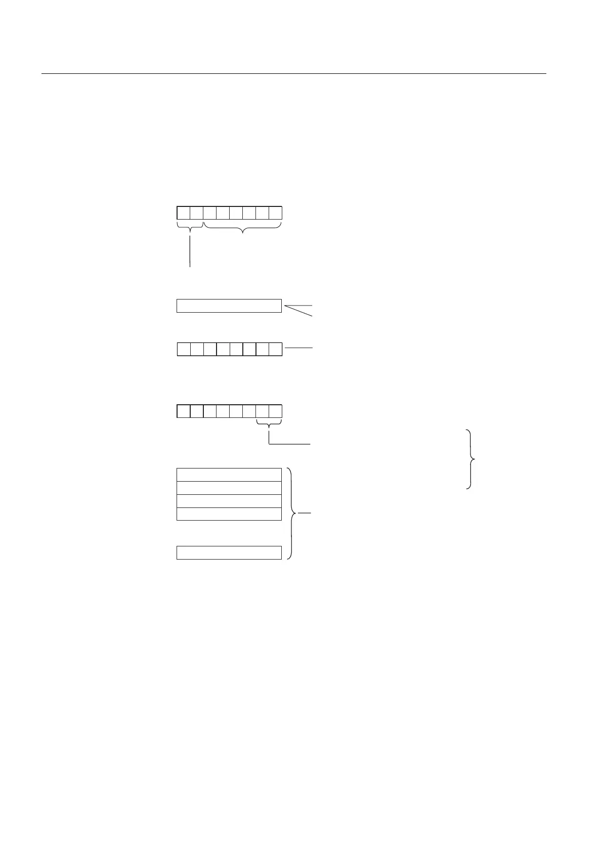
Structure of the interrupt status:
The interrupt status of module diagnostics provides details on a DP slave. Device-specific
diagnostics starts at byte y and has a maximum length of 20 bytes.
The following figure describes the structure and content of the bytes for a configured address
area of transfer memory.
Byte y+1
Byte y+4
to
Byte y+7
Byte y
Byte y+3
Byte z
7 654 3210
00
76 543 210
Byte y+2
000
0
00
Diagnostic data or interrupt data
.
.
.
Bit no.
Bit no.
Length of device-specific diagnostics incl. byte y
(max. 20 byte)
Code for module diagnostics
01H: Code for diagnostic interrupt
02H: Code for process interrupt
Slot no.
2 CPU
4...35 Number of
intermediate memory
00 No further information
about diagnostics status
01 Incoming diagnostics
(at least one error is present)
10 Outgoing diagnostics
11 Outgoing diagnostics
deviating error present
diagnostic interrupts only
Example for byte y+2:
CPU: =02H
1st address area: =04H
2nd address area: =05H
etc.
Figure 10-5 Device-specific diagnostics
Structure of the interrupt data for a process interrupt (from byte y+4)
When a process interrupt occurs (code 02
H
for process interrupt in byte y+1), 4 bytes of
interrupt information after byte y+4 are transferred. These 4 bytes are transferred to the
intelligent slave using SFC 7 "DP_PRAL" or SFC 75 "SALRM" when the process interrupt for
the master was generated.

 Loading...


