Configuring
4.6 Distribution of modules to several racks
S7-300, CPU 31xC and CPU 31x: Installation
4-10 Operating Instructions, Edition 08/2004, A5E00105492-05
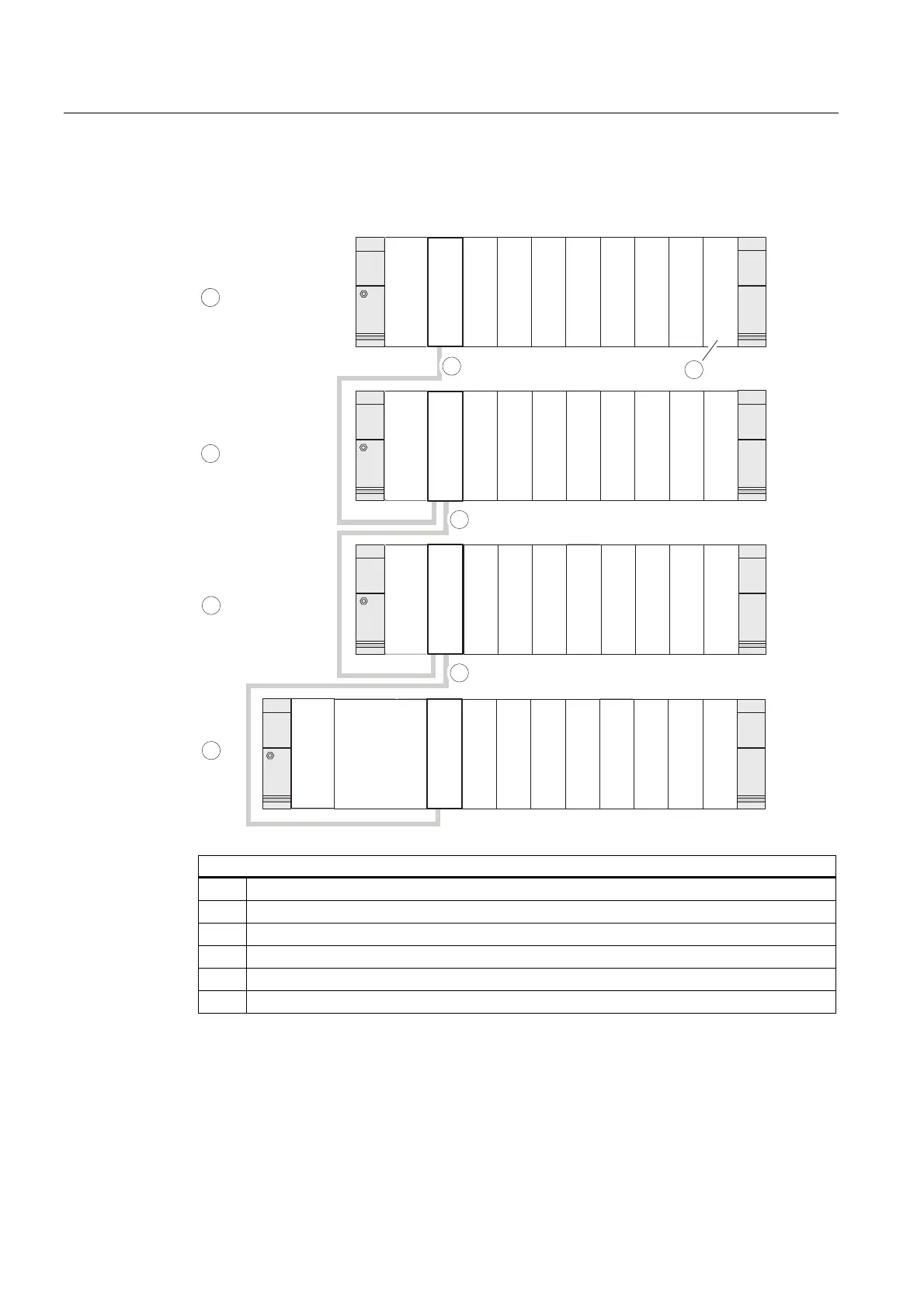
Example: Full assembly using four racks
The figure shows the arrangement of modules in an S7-300 assembly on 4 racks.
IM
IM
CPU
PS
SM1
SM2
SM3
SM4
SM5
SM6
SM7
SM8
PS
PS
4
3
2
1
5
4
6
SM1
SM2
SM3
SM4
SM5
SM6
SM7
SM8
SM1
SM2
SM3
SM4
SM5
SM6
SM7
SM8
SM1
SM2
SM3
SM4
SM5
SM6
SM7
SM8
IM
IM
IM
IM
5
5
The figure illustrates the following
(1) Rack 0 (central unit)
(2) Rack 1 (expansion module)
(3) Rack 2 (expansion module)
(4) Rack 3 (expansion module)
(5) The connecting cable 368
(6) Restriction for CPU 31xC. When this CPU is used, do not insert SM 8 into Rack 4.

 Loading...


