Installing
5.3 Mounting modules onto the rail
S7-300, CPU 31xC and CPU 31x: Installation
5-8 Operating Instructions, Edition 08/2004, A5E00105492-05
Installation steps
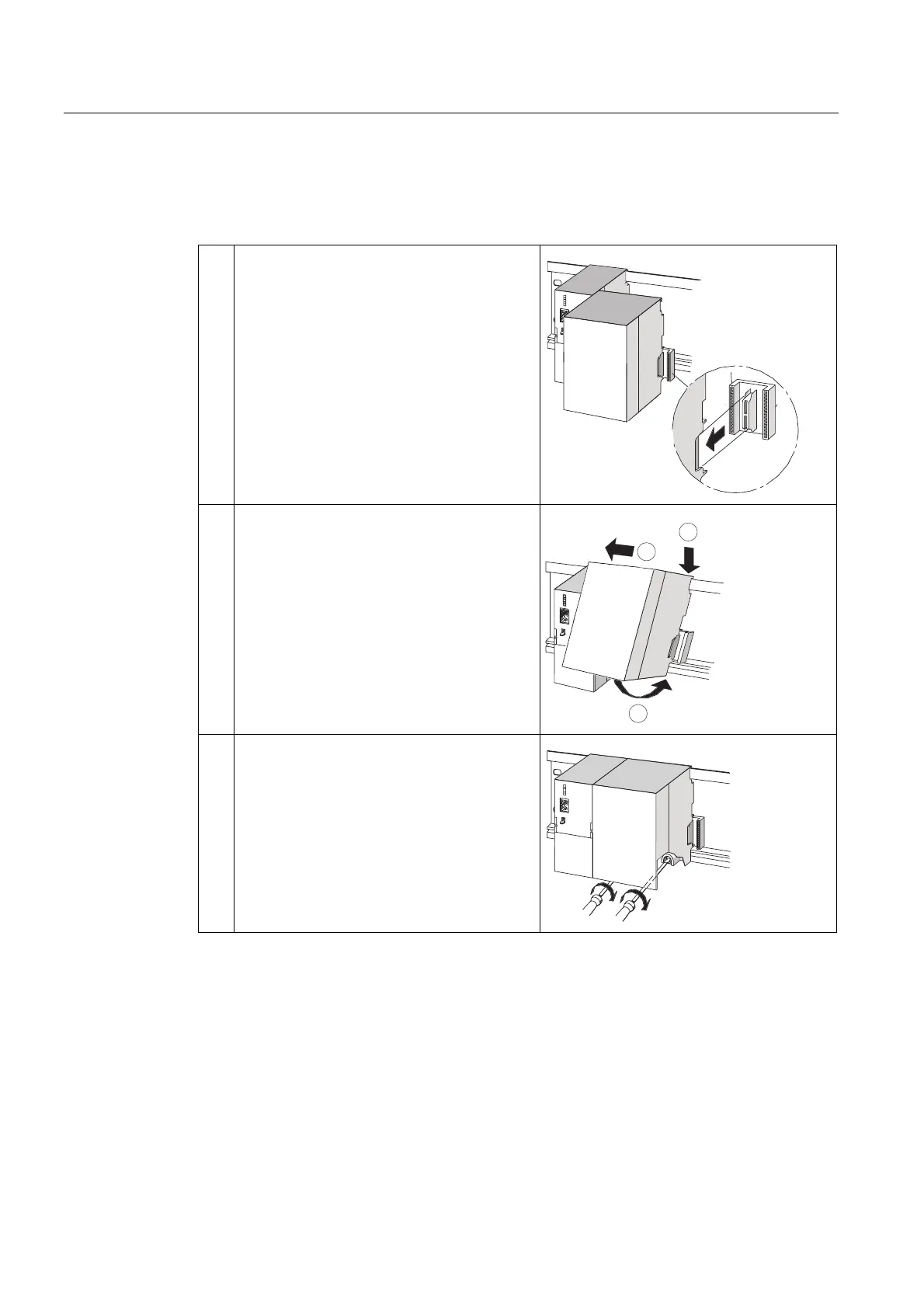
The various steps in module installation are explained below.
1. Plug the bus connectors into the CPU and SMs
/ FMs / CPs / IMs.
Except for the CPU, each module is supplied
with a bus connector.
• Always start at the CPU when you plug in
the bus connectors. Remove the bus
connector from the "last" module of the
assembly.
• Plug the bus connectors into the other
modules.
The "last" module does not receive a bus
connector.
CPU
2. Add all modules to the rail in the specified order
(1), slide them up to the module on the left (2),
then swing them down (3).
CPU
2
1
3
3. Screw-tighten the modules.
CPU
See also
Configuring an S7-300 with ungrounded reference potential (not CPU 31xC) (Page 4-17)

 Loading...


