Operator controls and indicators
3
Operator controls and indicators of the CPU
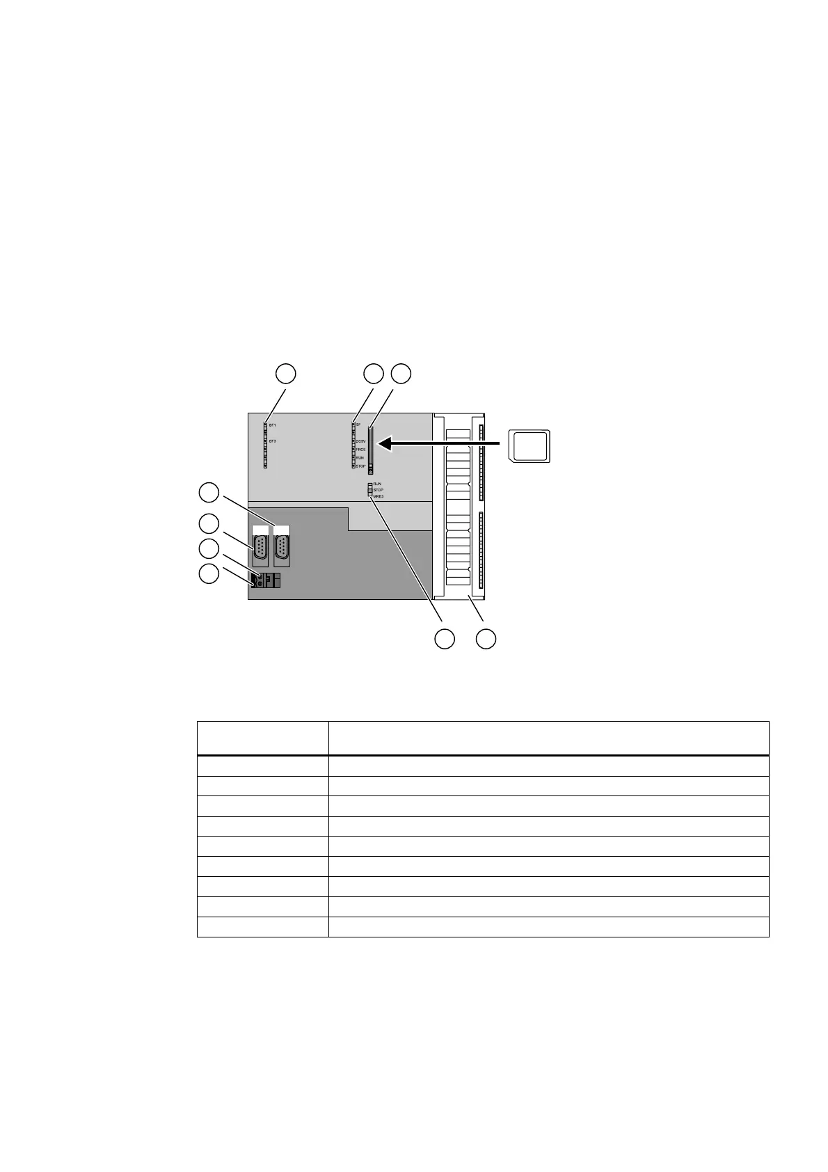
The following diagram shows the operator controls and indicators on the Technology CPU.
;
;
;
00&
Figure 3-1 Operator controls and indicators of the Technology CPU
Table 3-1 Operator controls and indicators of the Technology CPU
The number in the
diagram
points to the following element on the Technology CPU
1 Bus error indicators
2 Status and error displays
3 Slot for the Micro Memory Card (MMC), incl. the ejector
4 Connection of the integrated I/Os
5 Mode selector switch
6 Power supply connection
7 Grounding slide
8 Interface X1 MPI/DP
9 Interface X3 DP(DRIVE)
Integrated inputs and outputs for integrated technology
You can use the integrated technology inputs and outputs for technology functions and
configure them using
S7T Config
(included in the optional package
S7-Technology
).
S7-300 CPU Data: CPU 315T-2 DP
Manual, 12/2005, A5E00427933-02
3-1
 Loading...


