Cycle and response times
7.3 Response time
7.3.2 Shortest response time
Conditions for the shortest response time
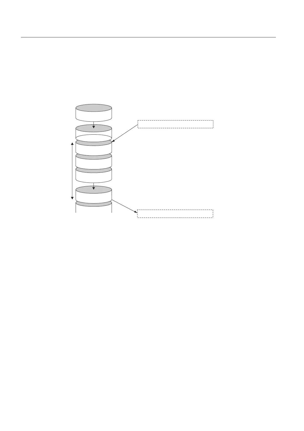
The following figure illustrates the conditions under which the shortest response time can be
achieved.
6&&%H6\
3,2
3,,
6&&%H6\
3,2
,QSXWGHOD\
2XWSXWGHOD\
8VHUSURJUDP
5HVSRQVHWLPH
,PPHGLDWHO\EHIRUHWKH3,,LVUHDGLQWKHVWDWHRIWKH
UHOHYDQWLQSXWFKDQJHV7KHFKDQJHLQLQSXWVLJQDOLV
WKHUHIRUHDOVRLQFOXGHGLQWKH3,,
7KHFKDQJHLQLQSXWVLJQDOLVSURFHVVHGKHUHE\WKHXVHU
SURJUDP
7KHXVHUSURJUDPUHDFWLRQWRWKHFKDQJHLQLQSXWVLJQDOLV
WUDQVIHUUHGWRWKHRXWSXWVKHUH
Figure 7-6 Shortest response time
Calculation
The (shortest) reaction time is made up as follows:
• 1 x process image transfer time for the inputs +
• 1 x process image transfer time for the outputs +
• 1 x program processing time +
• 1 x operating system processing time at the SCC +
• Delay in the inputs and outputs
The result is equivalent to the sum of the cycle time plus the I/O delay times.
S7-300 CPU Data: CPU 315T-2 DP
7-12 Manual, 12/2005, A5E00427933-02
 Loading...


