Cycle and response times
7.3 Response time
DP Cycle Times on the PROFIBUS-DP Network
If you have configured your PROFIBUS DP network with
STEP 7
, then
STEP 7
will calculate
the typical DP cycle time that must be expected. You can then view the DP cycle time of
your configuration on the PG.
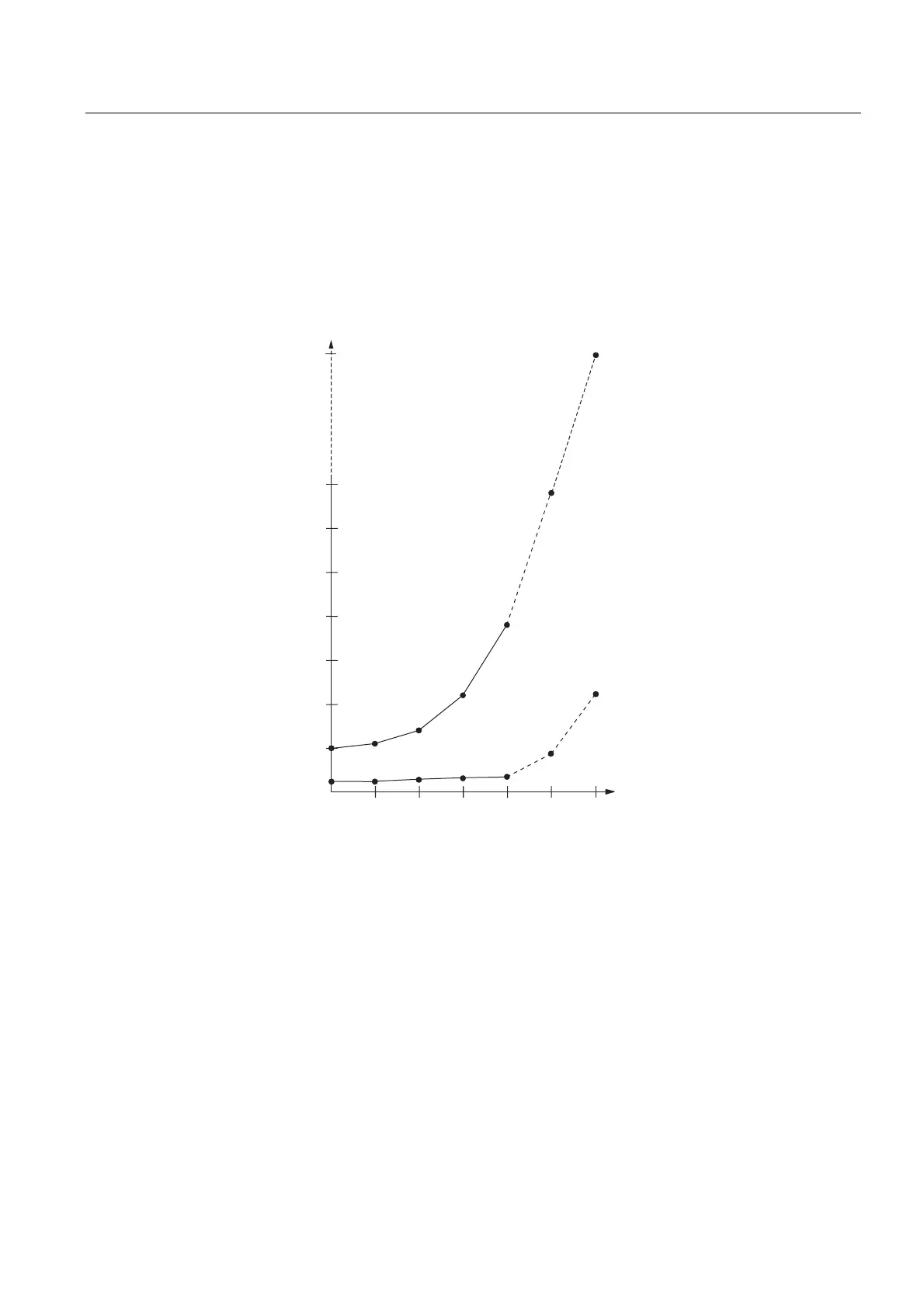
The figure below gives you an overview of the DP cycle time. We assume in this example
that each DP slave has 4 bytes of data on average.
P
s
P
s
P
s
PV
P
s
P
s
P
s
bPV
1XPEHURI'3VODYHV
PD[QXPEHU
GHSHQGVRQ&38
PLQVODYH
LQWHUYDO
%XVUXQWLPH
%DXGUDWH0EDXG
%DXGUDWH0EDXG
Figure 7-5 DP Cycle Times on the PROFIBUS-DP Network
With multi-master operation on a PROFIBUS-DP network, you must make allowances for the
DP cycle time at each master. That is, you will have to calculate the times for each master
separately and then add up the results.
S7-300 CPU Data: CPU 315T-2 DP
Manual, 12/2005, A5E00427933-02
7-11
 Loading...


