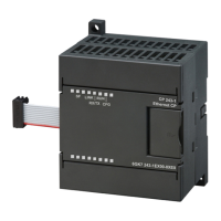
Mounting the CP 440
4.2 Mounting and Dismounting the CP 440
Point-to-point connection CP 440 Installation and Parameter Assignment
62 Manual, 09/2007, A5E00057742-03
4.2 Mounting and Dismounting the CP 440
Introduction
When mounting and removing the CP 441, you must observe certain rules.
Tool
You will need a 3.5 mm cylindrical screwdriver to mount or dismount the communication
processor.
Note
The CP 440 can be hot-plugged and hot-pulled, in other words with voltage applied. This
means that the CP 440 can be replaced while the programmable logic controller is in
operation. To avoid the CPU going into STOP, OB 83 (insert/remove interrupt) and OB 122
(I/O access error) must be programmed.The CP 440 is configured automatically when it is
plugged in. The CP 440 then resumes operation.
Installation Guidelines
The general installation guidelines for S7-400 must be observed (see the
S7-400/M7-400
Programmable Controller, Hardware and Installation
manual).
To meet the EMC (electromagnetic compatibility) values, the cable shield must be connected
to a shield bus.
4.2.1 Installation steps
To mount the communication processor in a rack, proceed as follows:
1. Remove the filler panel from the slot you want to use by gripping it where marked and
pulling it toward you. Insert the CP 441 module and tilt it downward.
2. Hang the communication processor in the rack and swing it down.
3. Screw down the module at the top and bottom with a torque of 0.8 to 1.1 Nm.
该文档是极速PDF编辑器生成,
如果想去掉该提示,请访问并下载:
http://www.jisupdfeditor.com/

 Loading...


