Notes on Configuration
S7-GRAPH for S7 300/400 Programming Sequential Control Systems
14-4 C79000-G7076-C526-01
T1
Trans1
2
Con...
T2
Trans2
S3
Uni...
T3
Trans3
T4
Trans4
"
ntr
lp
w
k"
"Hydraulic
_ok"
"Central_start
S1
Init
"Emer_off"
S5
Pro...
T5
Trans5
"Acknowledge"
Init
R "Unit_ready"
R "Process_enabled"
N "Controller_on"
MP
MD
Init.U
>=D
"Pneumatic
_ok"
Unit_ready
N "Unit_ready"
S4
Pro...
Process_enabled
N "Unit_ready"
N "Process_enabled"
"Door_
closed"
No_Process_enabled
T6
Trans6
"Hydraulic
ok"
"Pneumatic_
ok"
S2
T5
T6
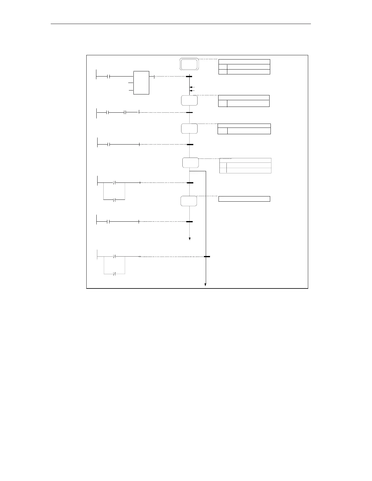
• After turning on the controller,
step 1 (initial step) is activated using the
INIT_SQ parameter and the signals Unit_ready and Process_enabled are reset.
• After a specified minimum waiting time,
step 2 the hydraulic and pneumatic
units are turned on dependent on the signal Controlpow_ok (control voltage OK)
by the Controller_on action.
• After the feedback indicating that the hydraulic and pneumatic systems are OK,
step 3 outputs the message Unit_ready (to various recipients including the
central controller).
• Triggered by the signal "Central_start" (start main console of the production
equipment),
step 4 sets the unit to the ready state and enables automatic
execution.
• With "Emer_off" or loss of the signal "Door_closed", the change to
step 5
cancels the Process_enabled. If this is acknowledged, there is a jump to step 2.