Designing a Sequential Control System based on the Example of a Drill
S7-GRAPH for S7 300/400 Programming Sequential Control Systems
3-4 C79000-G7076-C526-01
Initial State
The initial state of the drill is defined as follows:
• The drill motor and cooling pump are stopped
• The carriage/drill is in the upper position
• There is no work piece in the clamping device
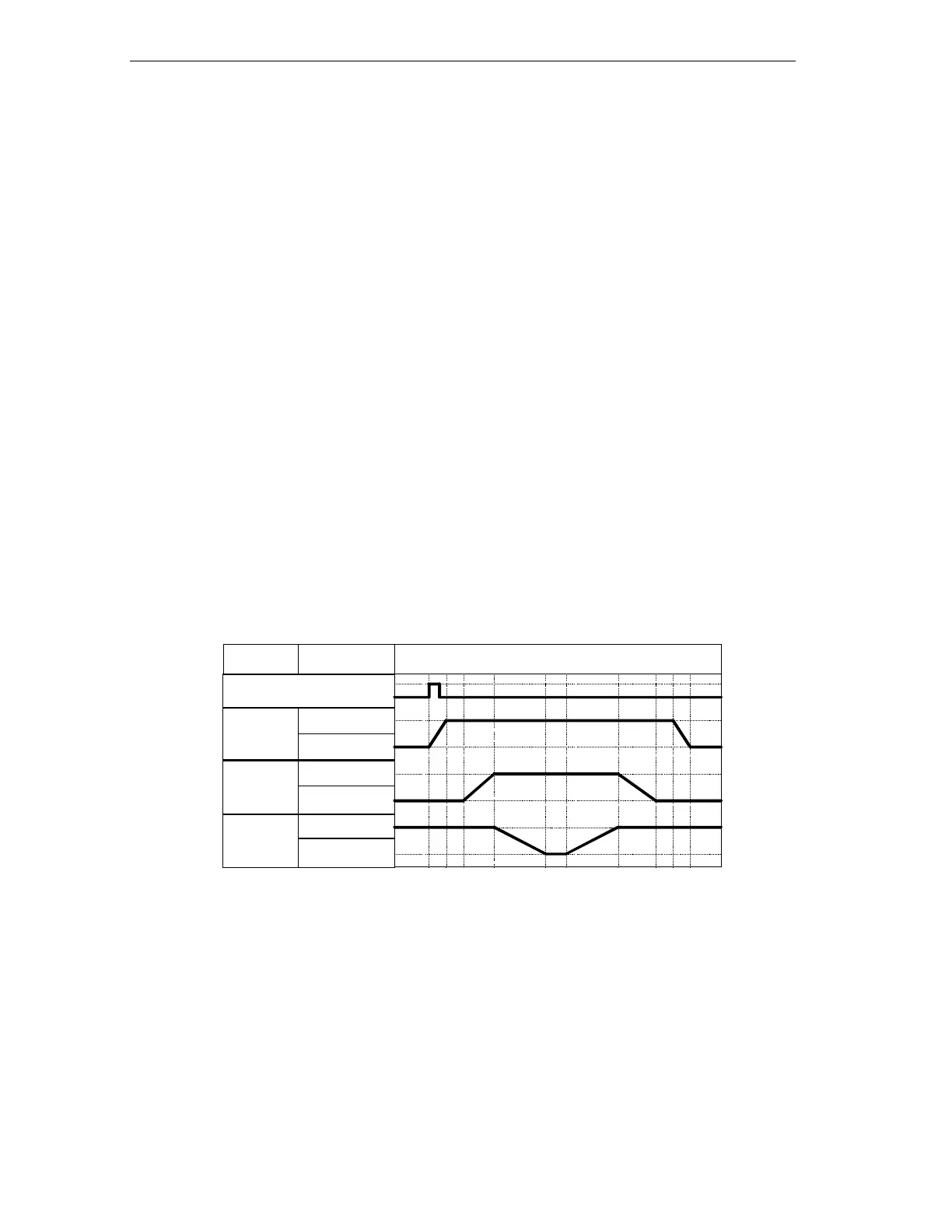
Functional Diagram - Drilling Sequence
The entire drilling sequence can be divided into the following sections:
• Insert work piece (manual)
• If required, set switch for coolant (depending on the material)
• Start the machine with the start button (drill motor starts up)
• Clamp the work piece with the selected clamp pressure
• Start the cooling pump (if coolant selected)
• Lower drill and carriage to the bottom target position (drill)
• Wait 0.5 seconds at lower target position (drill)
• Raise drill with carriage to upper target position
• Remove work piece, turn off drill motor and cooling pump
• Remove work piece (manual)
Motor
running
stopped
Carriage
up
down
Element State
Clamping
device
On
Off
Start
3.2 Selecting the Structure of the Sequencer
Before you write the program for the sequencer, you should include a concept
phase in which you break down the drilling operation into single steps. The basis of
the concept design is the technological drawing and the flowchart.