Designing a Sequential Control System based on the Example of a Drill
S7-GRAPH for S7 300/400 Programming Sequential Control Systems
3-8 C79000-G7076-C526-01
3.5 Creating a Symbol Table
When you program in STEP 7, you work with addresses such as I/O signals,
memory bits, counters, timers, data blocks, and function blocks. You can access
these addresses in your program in absolute format (for example I1.1, M2.0,
FB21).
You will find the program much clearer and easier to read if you use symbols (for
example Motor_A_on) instead of the absolute addresses. To allow the use of
symbols, you can enter a name, the absolute address, the data type and a
comment for every address used.
Once you have defined a symbol, it can be used throughout the entire user
program of a programmable module.
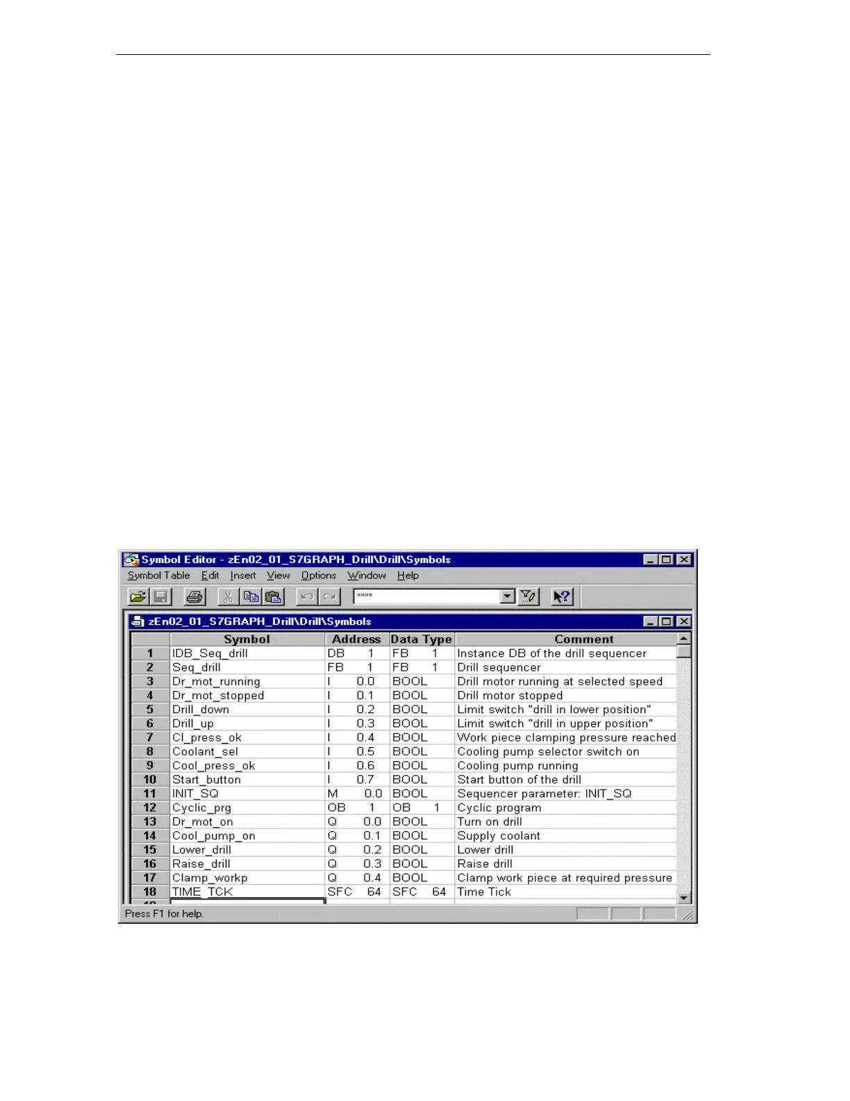
Creating a Symbol Table
If you want to write your program using symbolic addresses, it is advisable to
create the symbol table at this point.
1. Open the symbol table in the “Drill Program" folder by double-clicking
“Symbols".
2.
Edit the table as shown below.
3.
Save the symbol table using the menu command Table > Save.