Designing a Sequential Control System based on the Example of a Drill
S7-GRAPH for S7-300/400 Programming Sequential Control Systems
C79000-G7076-C526-01
3-3
3.1 Technological Task and Functional Diagram
Task
You want to program a sequential control system to automate a drill. The setup of
the drill is shown by a technological drawing and the process sequence in the form
of a function diagram.
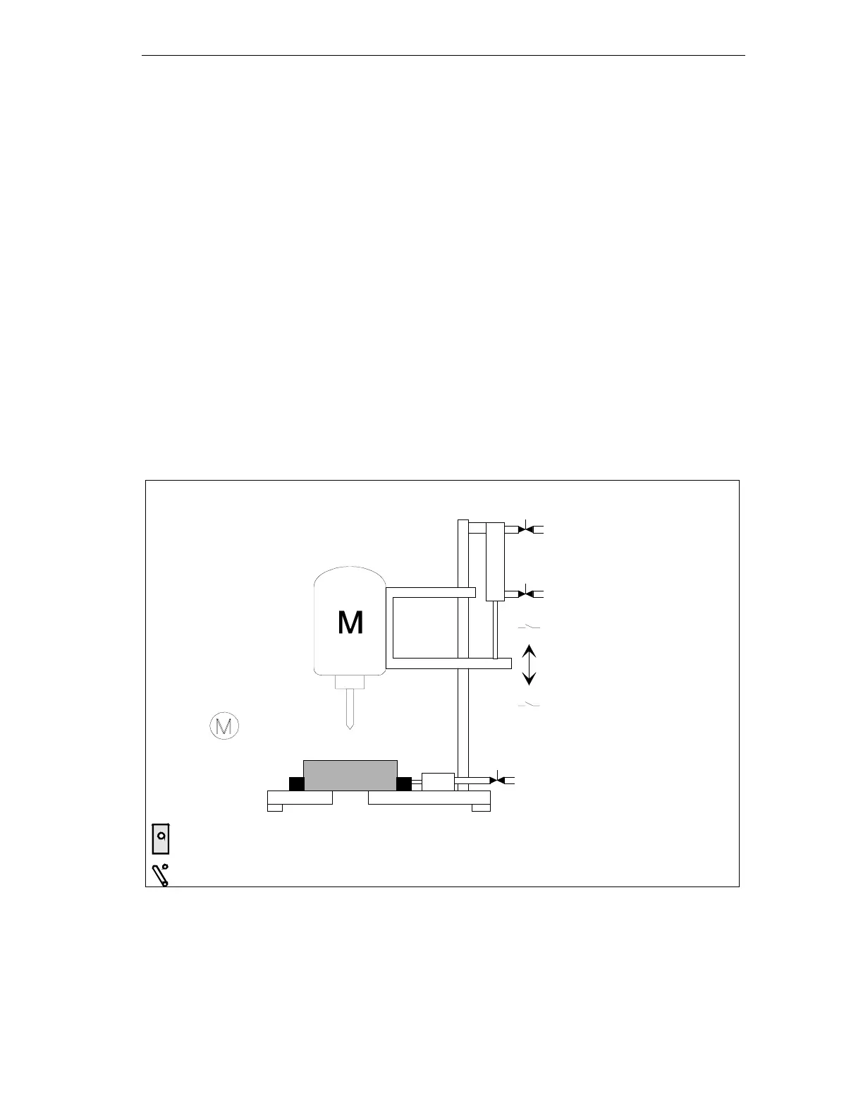
Technological Drawing - Set Up of the Drill
The drill consists of the following elements:
• Drill motor with feedback signals for drill running/stopped
• Start button and coolant switch
• Cooling pump with feedback signal for coolant pressure reached
• Clamping device with feedback signal for selected clamp pressure reached
• Carriage raise/lower drill with limit switches for drill up/down
Raise drill
Drill motor on
Feedback signal:
- Drill running
- Drill stopped
Coolin
pump on
Feedback signal
Coolant pressure reached
Start button
Feedback signal:
Selected clamping pressure
reached
Limit switch:
Drill up
Limit switch:
Drill down
Coolant switch
Drill motor
Carriage
Clamp device
Cooling pump
Lower drill