Designing a Sequential Control System based on the Example of a Drill
S7-GRAPH for S7 300/400 Programming Sequential Control Systems
3-2 C79000-G7076-C526-01
Requirements
To allow you to program and test the "drill" example, you require the following
hardware and software:
• Programming device/PC with
- STEP 7 standard package and the S7-Graph optional package
- MPI connection to the programmable logic controller
• A programmable logic controller (in our example an S7-300) consisting of the
following: standard rail, 24V power supply, CPU 314 and a digital input/output
module (8DI + 8DO)
• As an alternative to the PLC: The "PLC Simulation" S7 optional package
Procedure for Creating a Sequential Control System
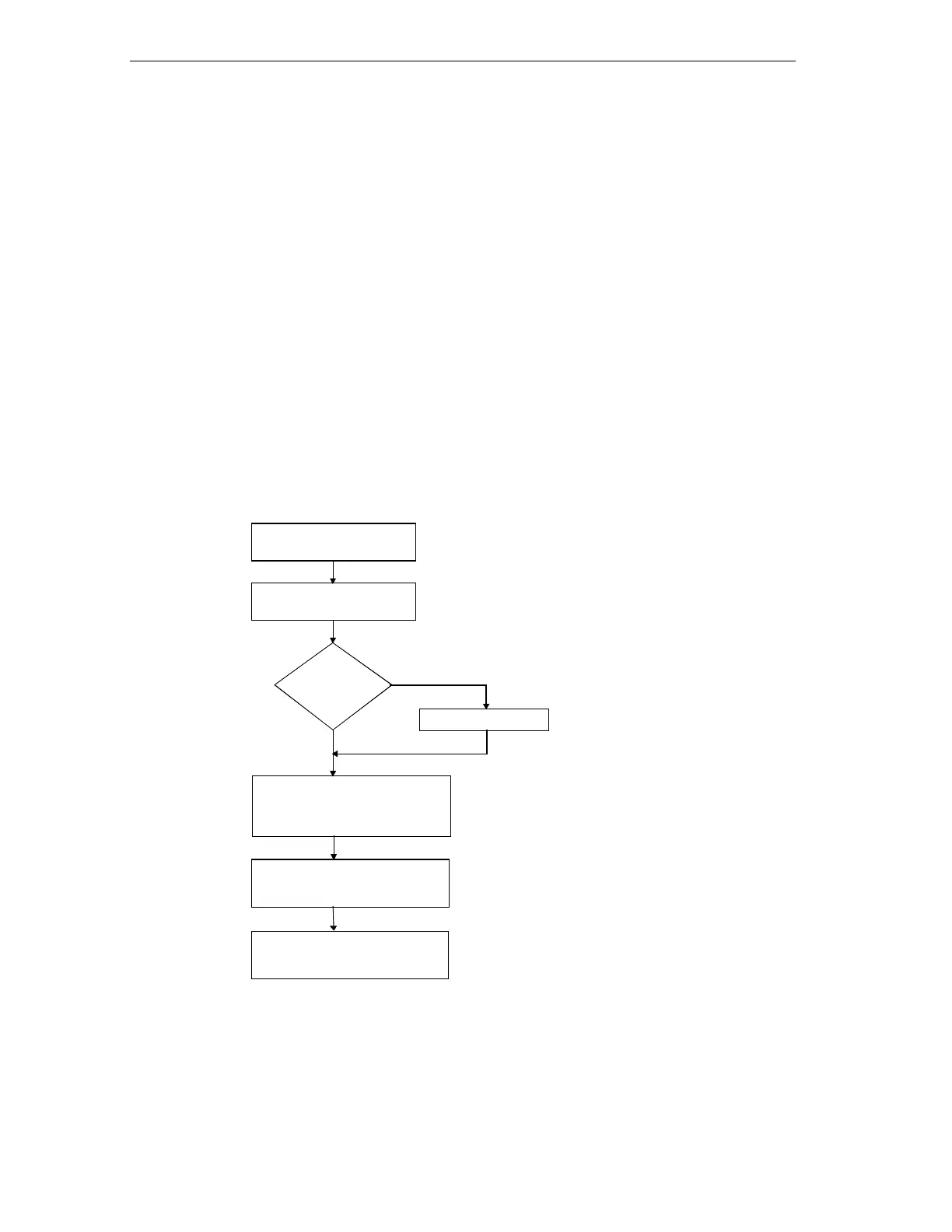
The flow diagram illustrates the procedure for creating the sequential control
system for the drill example:
Create symbol table
Specify structure of sequencer
and define signals for system
Create drill project in the
SIMATIC Manager
Create sequencer:
•
create and open S7 Graph FB1 in
the SIMATIC Manager
•
Program sequencer
Program OB1 with FB1 call and
corresponding instance DB (DB1)
Download sample program (DB1, FB1,
OB1) to the CPU in the SIMATIC
Manager and test the sequencer
Symbolic
programming
yes
no