Designing a Sequential Control System based on the Example of a Drill
S7-GRAPH for S7-300/400 Programming Sequential Control Systems
C79000-G7076-C526-01
3-5
Dividing the Drilling Process into Individual Steps - Structure of the Sequencer
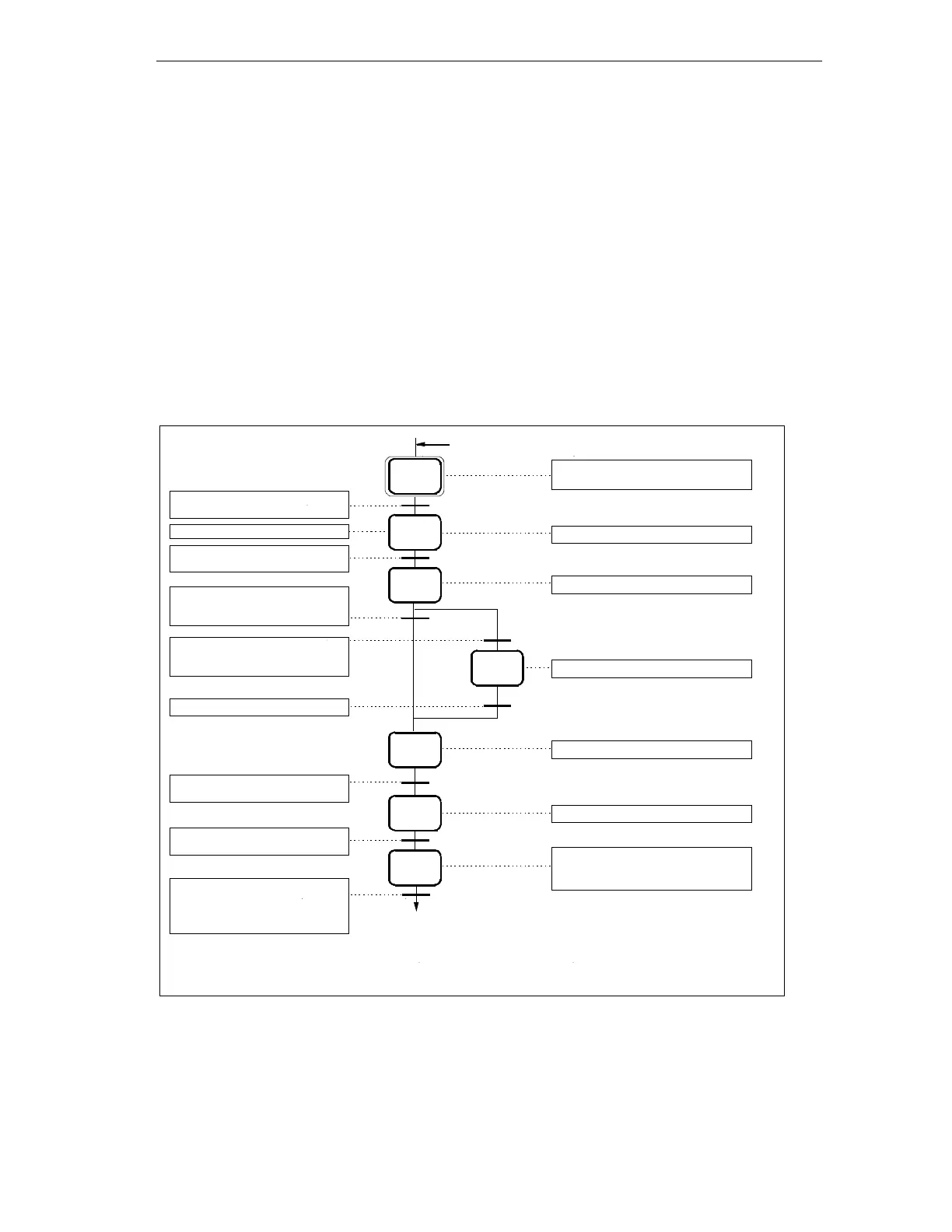
The drilling process is described by S7-Graph in the form of a sequencer. A
sequencer represents a sequence of single steps and conditions that control how
the process moves on to the next single step. To specify the structure of the
sequencer, follow the steps outlined below:
1. Break down the drilling process into steps and specify the order of the steps (for
example “step S2 follows S1" or “step S3 follows either step S4 or S7").
2.
For each step, specify the actions that must be performed in the step (for
example in S1 the action “Drill ready" or in S3 the action “Turn on drill motor").
3.
Then decide for every step which conditions must be met so that the process
can move on to the next step (for example for T1 the condition “Drill started -
start button pressed" or for T5 the condition “Drill in upper position").
T2
S2
T8
T3
T7
S3
S1
T4
T1
T6
S7
S4
Drill ready (initial step)
Clamp work piece
Turn on drill motor
Turn on cooling pump
Lower drill (start drilling)
Drill program started (start button
pressed)
Work piece clamped with selected
pressure
Drill motor running at selected speed
(without coolant)
Coolant pressure reached
Drill in lower position
Drill motor running at selected speed
(with coolant)
S5
S6
T5
T6
S1
Raise drill
Release work piece, turn off drill motor
and cooling pump
Drill in upper position
Work piece is released, cooling
pump stopped, drill motor stopped
Waiting time 500 ms
S = step
T = transition
Monitor clamping