4 Installing Router Kit components in the installation enclosure
4.4 Installing the Router Kit WLAN / LAN in the installation enclosure
Application example for SIMOTICS CONNECT 400 - Router KitInbetriebnahme- und Montagehandbuch 30
23. Pull the cables through the pre-drilled holes at the bottom and secure the cable glands
with the locknuts.
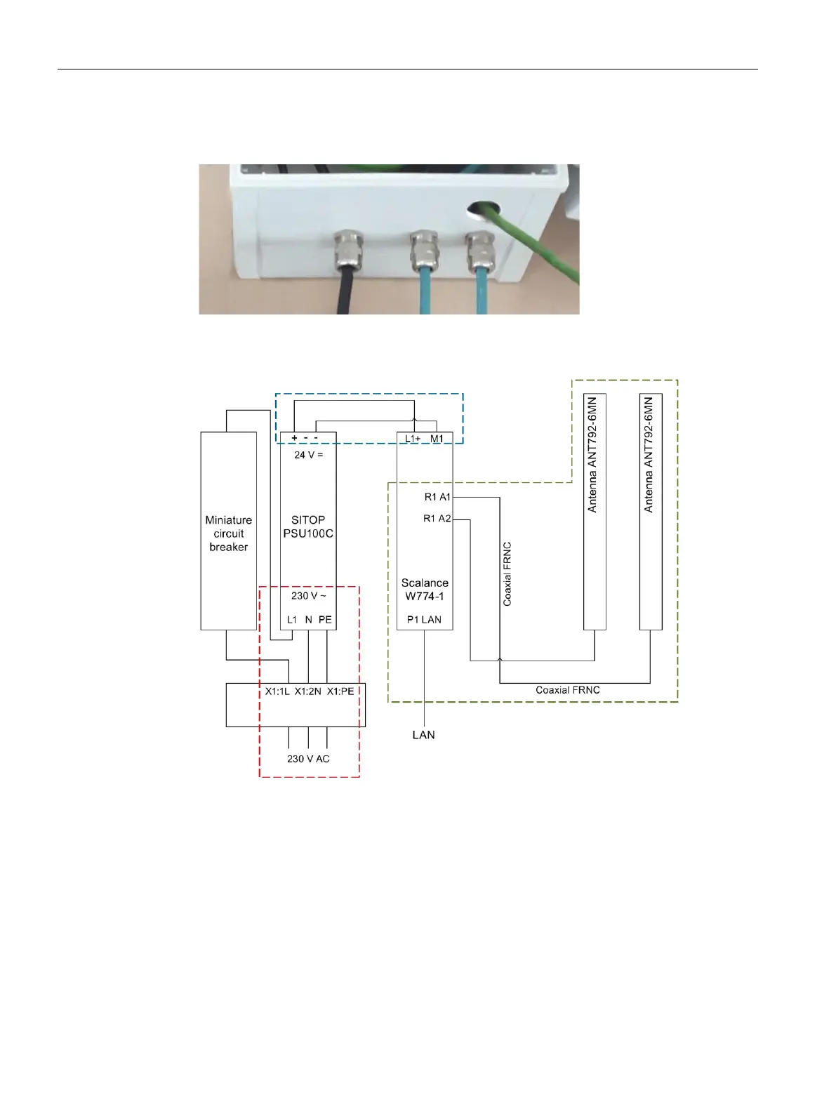
Figure 4-20 Attached cable glands
24. Wire the elements as shown in the terminal connection diagram.
Figure 4-21 Terminal connection diagram
Attachment of antenna cable between SCALANCE W774-1
(connection: R1 A1, R1 A2) and the two antennas ANT792-6MN