4. When positioning the machine, ensure that a uniform axial gap (y→0) is maintained around
the coupling.
5. Fix the machine to the foundation. The choice of fixing elements depends on the foundation
and is the plant operator's responsibility.
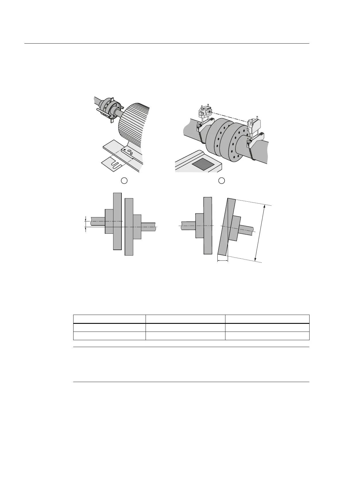
① Plates placed under the motor for alignment
② Laser alignment
Image 5-2 Schematic diagram: Aligning the machine to the driven machine
Table 5-2 Permissible deviations for aligning the machine with flexible coupling
Max. speed n
max
Max. parallel offset x Max. angular offset y
n
max
≤ 1500 rpm x
max
= 0.08 mm y
max
= 0.08 mm / 100 mm ∅ D
1500 rpm <
n
max
≤ 3600 rpm x
max
= 0.05 mm y
max
= 0.05 mm / 100 mm ∅ D
Note
Machine expansion
When performing alignment, make allowance for the thermal expansion of the machine due
to rising temperature.
Assembling
5.3 Installing the machine
SIMOTICS DC 1GG6
48 Operating Instructions 02/2016