6.5 Connecting the main circuit
Requirements
● Remove the insulation from the conductor ends so that the remaining insulation is almost
long enough to reach the cable lug.
● Insulate the cable lug sleeves to ensure minimum air clearances are maintained.
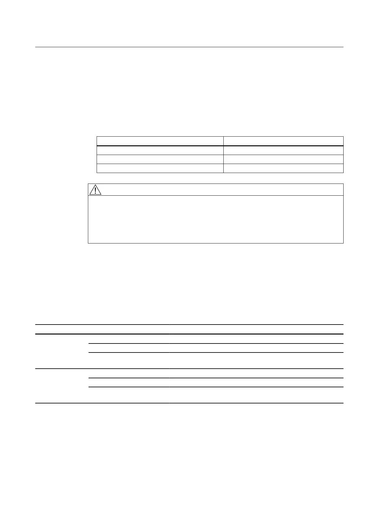
Voltage Minimum air clearance
Up to 600 V > 8 mm
Up to 800 V > 10 mm
Up to 1200 V > 14 mm
WARNING
Short circuits caused by projecting wire ends
The minimum air clearance by be reduced by projecting wire ends. This can result in short
circuits. This can result in death, serious injury or material damage.
Remove protruding cables. Ensure that minimum air clearances as specified in the table
above are maintained.
Connecting using cable lugs
1. Select the cable lugs corresponding to the required cable cross-section and the specified
dimensions of the terminal connection.
2. Tighten the contact and fastening nuts to the torque specified in the table below:
Table 6-2 Terminal box connection data
Terminals 1XB7 gk 602 / gk 604 gk 702 / gk 704
Main terminals Terminal size M16 M10 M12
Tightening torque 83 Nm 13 Nm 20 Nm
Connectable cable cross-sec‐
tion
6 x 240 mm
2
2 x 35 mm
2
2 x 70 mm
2
Auxiliary terminals Terminal size M6 M4 M4
Tightening torque 4 Nm 1.2 Nm 1.2 Nm
Connectable cable cross-sec‐
tion
35 mm
2
6 mm
2
6 mm
2
Electrical connection
6.5 Connecting the main circuit
SIMOTICS DC 1GG6
Operating Instructions 02/2016 55