Point of application of radial forces F
R
at the shaft extension
F
R
Point of application of the radial force
x Distance between where the radial force is applied and the shaft shoulder in mm
Figure 3-1 Force application point at the shaft extension
The following diagrams indicate the maximum permissible radial force for the corresponding
motor frame size. It depends on the force application point and the average speed for a nominal
bearing service life (L10h) of 25000 h.
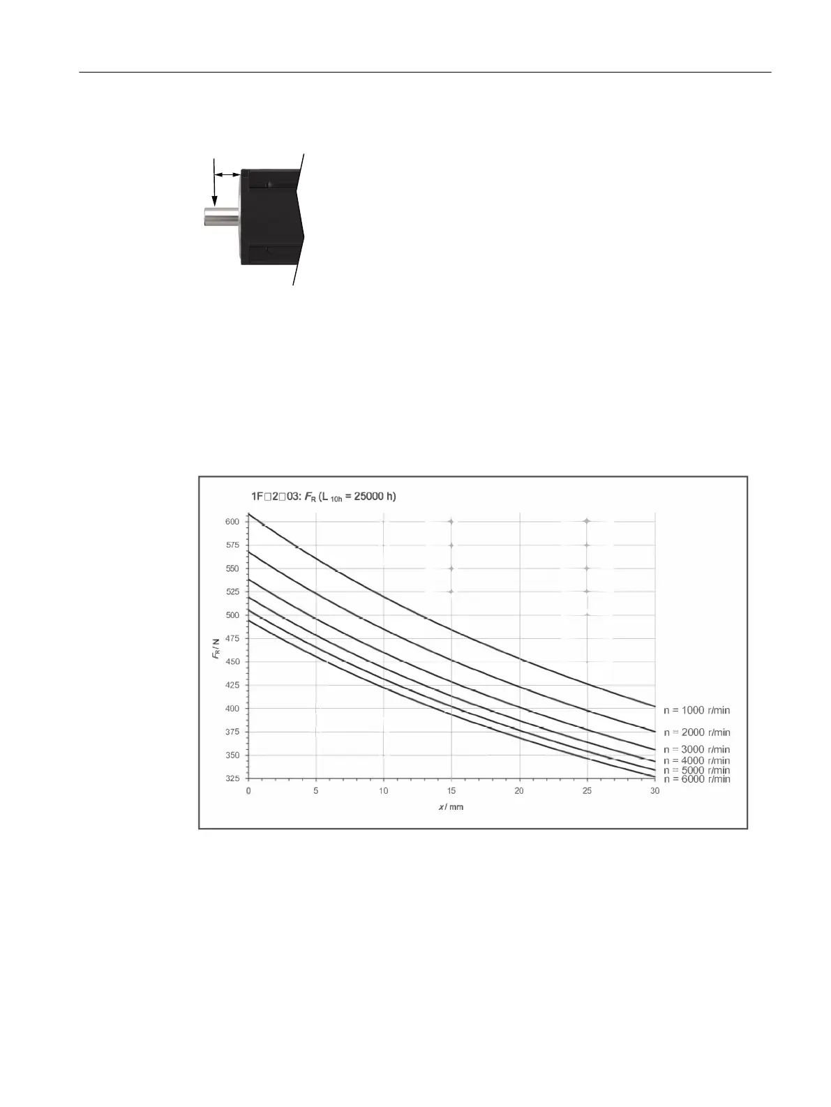
Radial force diagram 1F☐2☐03
Figure 3-2 Maximum permissible radial force F
R
at a distance x from the shaft shoulder for a nominal
bearing lifetime of 25000 h.
Mounting and options
3.4 Permissible radial and axial forces
SIMOTICS S-1FK2 synchronous motors for SINAMICS S120
Operating Instructions, 02/2022, A5E46089564B AD 37