0 M01 PRO‐
GRAM
TEST
MDA SINGLE
BLOCK
AUTO REF.
POINT
JOG HAND
WHEEL
1 Key 7 TAIL
STOCK
INT. EXT. CHUCK TOOL
CHANGE
COOLANT LAMP ROV
2 100 (INC) 10 (INC) 1 (INC) Key 12 Key 11 Key 10 Key 9 Key 8
3 Axis tra‐
versing key
(↑x)
Key 13 CYCLE
START
CYCLE
STOP
RESET SPINDLE
RIGHT
SPINDLE
STOP
SPINDLE
LEFT
4 Key 21 Axis tra‐
versing key
(↓x)
Key 19 Axis tra‐
versing key
(→z)
RAPID Axis tra‐
versing key
(←z)
Key 15
8 1
1)
1
1)
7 SEG LED1
2)
9 1
1)
1
1)
7 SEG LED2
2)
1)
To ensure the correct display of the active tool number, make sure that you set Bit 4 and Bit 5 to 1.
2)
You can set only values 0 to 9 for each 7-segment LED (LED1 and LED2).
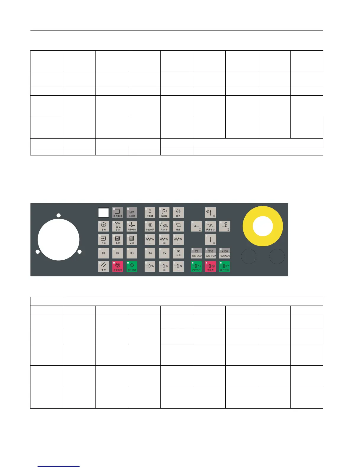
Horizontal MCP with a reserved slot for the handwheel
From the MCP
DB1000 From the MCP [r]
Byte Bit 7 Bit 6 Bit 5 Bit 4 Bit 3 Bit 2 Bit 1 Bit 0
0 Key 2 Key 1 MDA SINGLE
BLOCK
AUTO REF. POIN
T
JOG HAND
WHEEL
1 Feed over‐
ride key (-)
TAIL
STOCK
INT. EXT. CHUCK TOOL
CHANGE
COOLANT LAMP Key 3
2 100 (INC) /
100% G00
10 (INC) /
50% G00
1 (INC) /
25% G00
F0 G00 Key 5 Key 4 Feed over‐
ride key (+)
Feed over‐
ride key
(100%)
3 Axis tra‐
versing key
(↑x)
Spindle
override
key (-)
CYCLE
START
CYCLE
STOP
RESET SPINDLE
RIGHT
SPINDLE
STOP
SPINDLE
LEFT
4 M01 PRO‐
GRAM
TEST
Axis tra‐
versing key
(↓x)
Spindle
override
key (+)
Axis tra‐
versing key
(→z)
RAPID Axis tra‐
versing key
(←z)
Spindle
override
key (100%)
PLC user interface
6.2 Signals from/to the MCP
Parameter Manual
474 List Manual, 01/2017
 Loading...


