By setting bit 1, the channel name stored in machine data MD20000 $MC_CHAN_NAME
can be programmed in the part program. The channel name can thus also be programmed
instead of a numerical value for the channel number in programming coordination
commands such as (START(), INIT(), WAIT() etc.)
2: 0x4 Reserved
3: 0x8 Convert illegal ASCII characters into blanks
By setting bit3, the previous behavior is activated when interpreting a part
program block. This means that all invalid ASCII characters in a part program block
are handled internally as blank.
4: 0x10 The wait time G4 F<wait time> is rounded off as a multiple integer
of an IPO cycle.
This means that a G4 F0.001 only takes one cycle, for an IPO cycle of 1 msec.
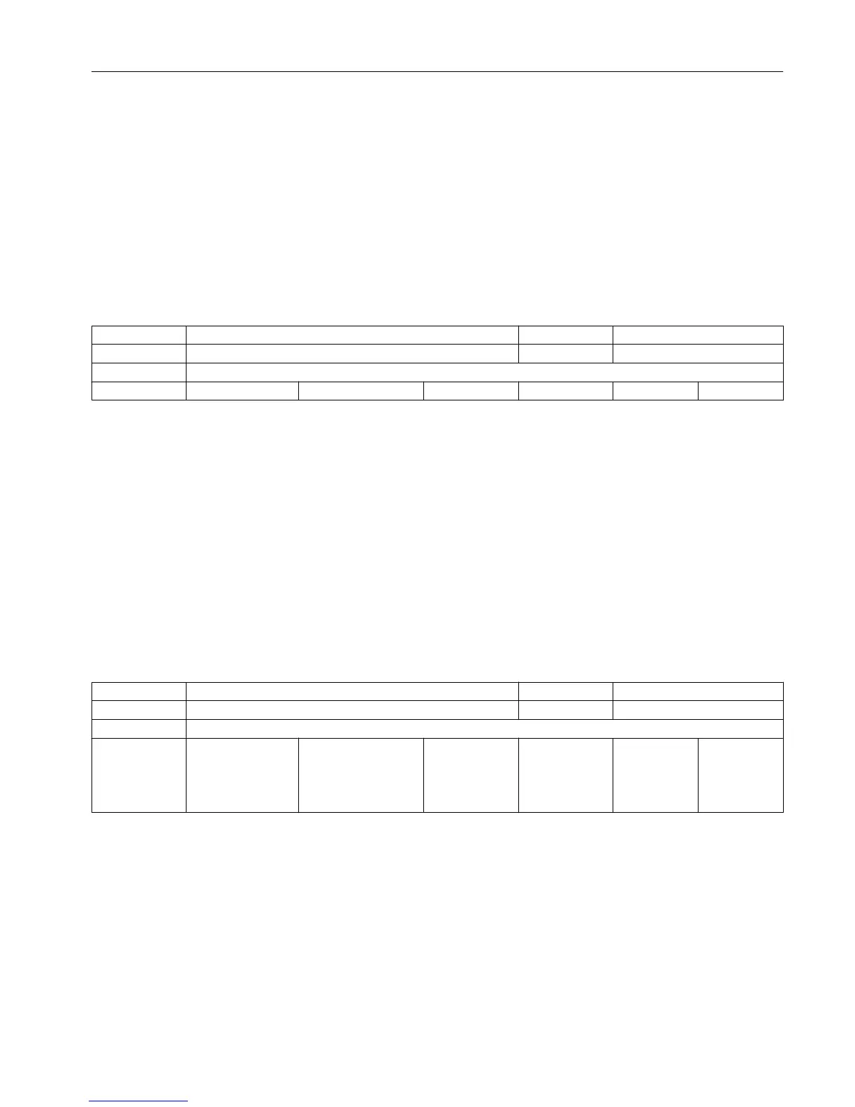
10284 DISPLAY_FUNCTION_MASK EXP, N01 -
- Behavior of various display variables DWORD PowerOn
-
- - 0x0 0 0x7FFFFFFF 1/1 M
Description: Bit mask for parameterizing various display variables:
BitNo. Hexadec. Meaning with bit set
value
Bit0: 0x1
Parameters are assigned to the OPI variable lastBlockNoStr in the SPARP and SPARPP
blocks.
Bit1: 0x2
Concerns the OPI variable cmdSpeed in the SPARPP block. If the bit is set, the variable
returns
the programmed
speed even if the spindle is at a standstill or in another mode
(positioning mode, axis mode).
Bit2 0x4
Concerns the OPI variable cmdSpeed in the SPARPP block. (reserved for constant cutting
speed)
Bit8: 0x100
Servotrace manages larger numerical values internally. Overruns in data format are
avoided. The accuracy may be reduced with large numerical values.
10368 HW_ASSIGN_DIG_FASTOUT N10 A4
- Hardware assignment of external digital NCK outputs DWORD PowerOn
-
- 4 0x01000000,
0x01000000,
0x01000000,
0x01000000,
0x01000000, 0x01...
0x01000000 0x060003FF 2/2 M
Description: For PROFIBUS/PROFINET:
1st + 2nd byte indicate the logical start address of the I/O slot on the PROFIBUS/
PROFINET:
Value 0000 means NO active slot
Values 0001..0100 are reserved for the PLC process image (the value of input slots can
be
read by
the NCK without errors; however, output slots are forbidden in this range,
and cause an alarm on power up)
1st byte = LowByte of the logical start address
2nd byte = HighByte of the logical start address
3rd byte = 0 = without meaning
4th byte = 5 = segment no. for PROFIBUS/PROFINET
Machine data
3.2 General machine data
Parameter Manual
List Manual, 01/2017 39