6.13.2 Signals, synchronized actions from channel
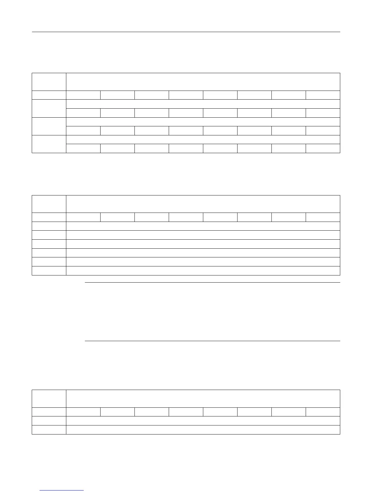
DB4700 Signals, synchronized actions from channel [r]
NCK -> PLC interface
Byte Bit 7 Bit 6 Bit 5 Bit 4 Bit 3 Bit 2 Bit 1 Bit 0
0 Synchronized action with ID...can be blocked from the PLC
ID8 ID7 ID6 ID5 ID4 ID3 ID2 ID1
1 Synchronized action with ID...can be blocked from the PLC
ID16 ID15 ID14 ID13 ID12 ID11 ID10 ID9
2 Synchronized action with ID...can be blocked from the PLC
ID24 ID23 ID22 ID21 ID20 ID19 ID18 ID17
6.13.3 Reading and writing PLC variables
DB4900 PLC variables [r/w]
PLC interface
Byte Bit 7 Bit 6 Bit 5 Bit 4 Bit 3 Bit 2 Bit 1 Bit 0
0 Offset [0]
1 Offset [1]
2 Offset [2]
… …
4094 Offset [4094]
4095 Offset [4095]
Note
The programming engineer (NCK and PLC) is responsible for organizing (structuring) this
memory area. Every
storage position in the memory can be addressed provided that the limit
is selected according to the appropriate data format (i.e. a 'DWORD' for a 4byte limit, a WORD
for a 2byte limit, etc.). The memory area is always accessed with the information about the
data type and the position offset within the memory area. The PLC variables can be read or
written in the NC program $A_DBB[n] ("n" stands for the position offset in bytes).
6.14 Axis actual values and distance-to-go
DB5700 ...
5704
Signals from axis/spindle [r]
NCK -> PLC interface
Byte Bit 7 Bit 6 Bit 5 Bit 4 Bit 3 Bit 2 Bit 1 Bit 0
0 Axis actual value (REAL)
4 Axis distance-to-go (REAL)
PLC user interface
6.14 Axis actual values and distance-to-go
Parameter Manual
504 List Manual, 01/2017