12.95
7-100
E Siemens AG, 2002. All rights reserved
SINUMERIK 810D Manual Hardware Configuration (PHC) -- 11.02 Edition
Watchdog
Time recording Disabling of the NC outputs,
LED (red) on
Hardware combination Hardware
configuration
Disabling of the NC outputs,
LED (red, yellow) on,
Status message to NC
The digital and analog outputs are switched to a safe status (0V at the output)
with the XOUTDS signal in the event of interference or faults in the NCU, in the
microcontroller and in the case of a power failure!
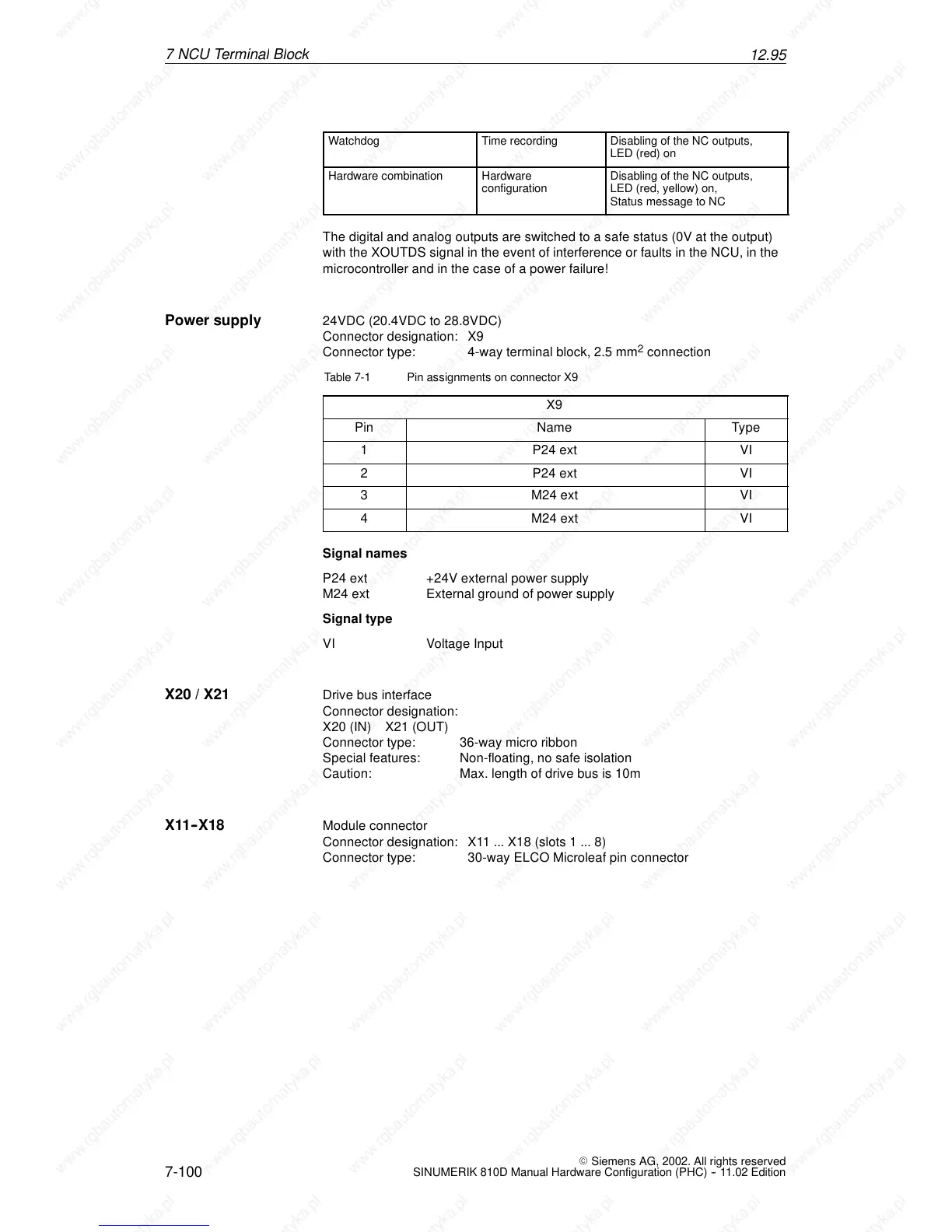
24VDC (20.4VDC to 28.8VDC)
Connector designation: X9
Connector type: 4-way terminal block, 2.5 mm
2
connection
Table 7-1 Pin assignments on connector X9
X9
Pin Name Type
1 P24 ext VI
2 P24 ext VI
3 M24 ext VI
4 M24 ext VI
Signal names
P24 ext +24V external power supply
M24 ext External ground of power supply
Signal type
VI Voltage Input
X Drive bus interface
Connector designation:
X20 (IN) X21 (OUT)
Connector type: 36-way micro ribbon
Special features: Non-floating, no safe isolation
Caution: Max. length of drive bus is 10m
Module connector
Connector designation: X11 ... X18 (slots 1 ... 8)
Connector type: 30-way ELCO Microleaf pin connector
Power supply
X20 / X21
X11--X18
 Loading...


