12.95
4.2 Interfaces of the SINUMERIK 810D
4-67
E Siemens AG, 2002. All rights reserved
SINUMERIK 810D Manual Hardware Configuration (PHC) -- 11.02 Edition
The DIP FIX switches inside the cable distributors 6FX 2006-1BA01 must be set
as follows:
Table 4-12 Setting the DIP--FIX switches (S1--S6) in the cable distributor
Switch
S1 S2 S3 S4 S5 S6
Open x x x x
Closed x x
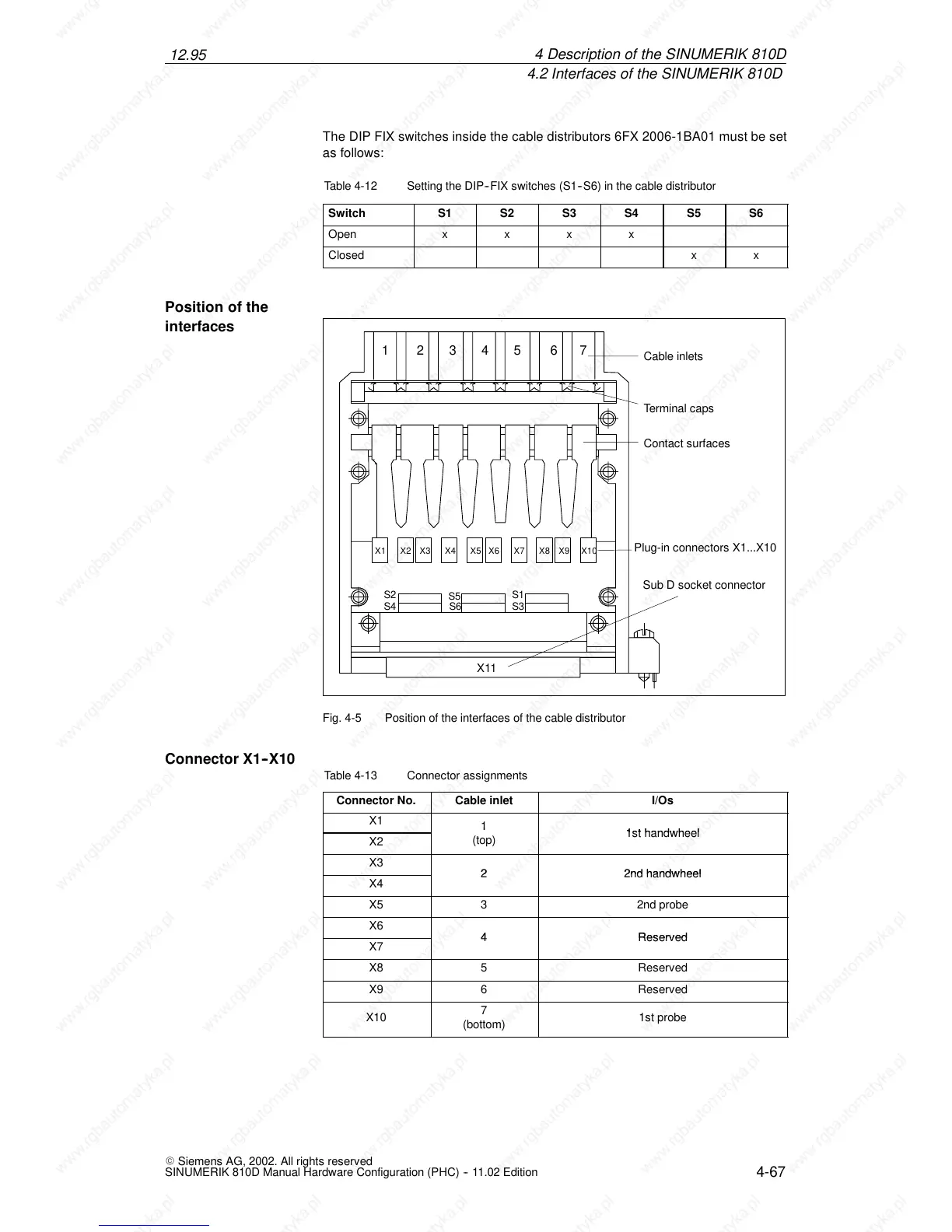
X1 X2 X4
X5
X6 X7 X8
X9 X10
X3
X11
Cable inlets
Terminal caps
Contact surfaces
Plug-in connectors X1...X10
S3S4
S5
S1S2
Sub D socket connector
S6
1 2345 67
Fig. 4-5 Position of the interfaces of the cable distributor
Table 4-13 Connector assignments
Connector No.
Cable inlet I/Os
X1
1
 Loading...


